Composite liquid die forging device and method for bottom shell workblank of electric vehicle battery

A technology for electric vehicles and liquid die forging, which is applied in the field of electric vehicle battery bottom case forging. It can solve problems such as unstable welding quality, easy deformation of wax molds, and limited feeding effect, so as to achieve less internal pores and inclusion defects, and no oxidation. And the effects of inclusion pollution and fine microstructure

Active Publication Date: 2018-11-16
BEIJING JIAOTONG UNIV
View PDF7 Cites 0 Cited by
  • Summary
  • Abstract
  • Description
  • Claims
  • Application Information

AI Technical Summary

Problems solved by technology

The aluminum alloy plate welding method is used to manufacture the blank of the electric vehicle battery bottom case. Due to the poor performance of the aluminum alloy welding joint, the welding quality is unstable, and there is a risk of weld cracking during use; the investment casting (also called precision casting) method is used to manufacture electric vehicles. Due to the large size and weight of the battery bottom case, the wax mold is easy to deform, and often has defects such as pores and inclusions, poor quality stability, and low material utilization; The aluminum alloy inside is hydraulically injected into the mold cavity, cooled and solidified to form, because of the low pressure, the workpiece contour size is too large, the feeding effect is limited, the incidence of shrinkage defects is high, and the scrap rate is as high as 40% or more

Method used


Image

  • Composite liquid die forging device and method for bottom shell workblank of electric vehicle battery
  • Composite liquid die forging device and method for bottom shell workblank of electric vehicle battery
  • Composite liquid die forging device and method for bottom shell workblank of electric vehicle battery

Examples


Embodiment 1

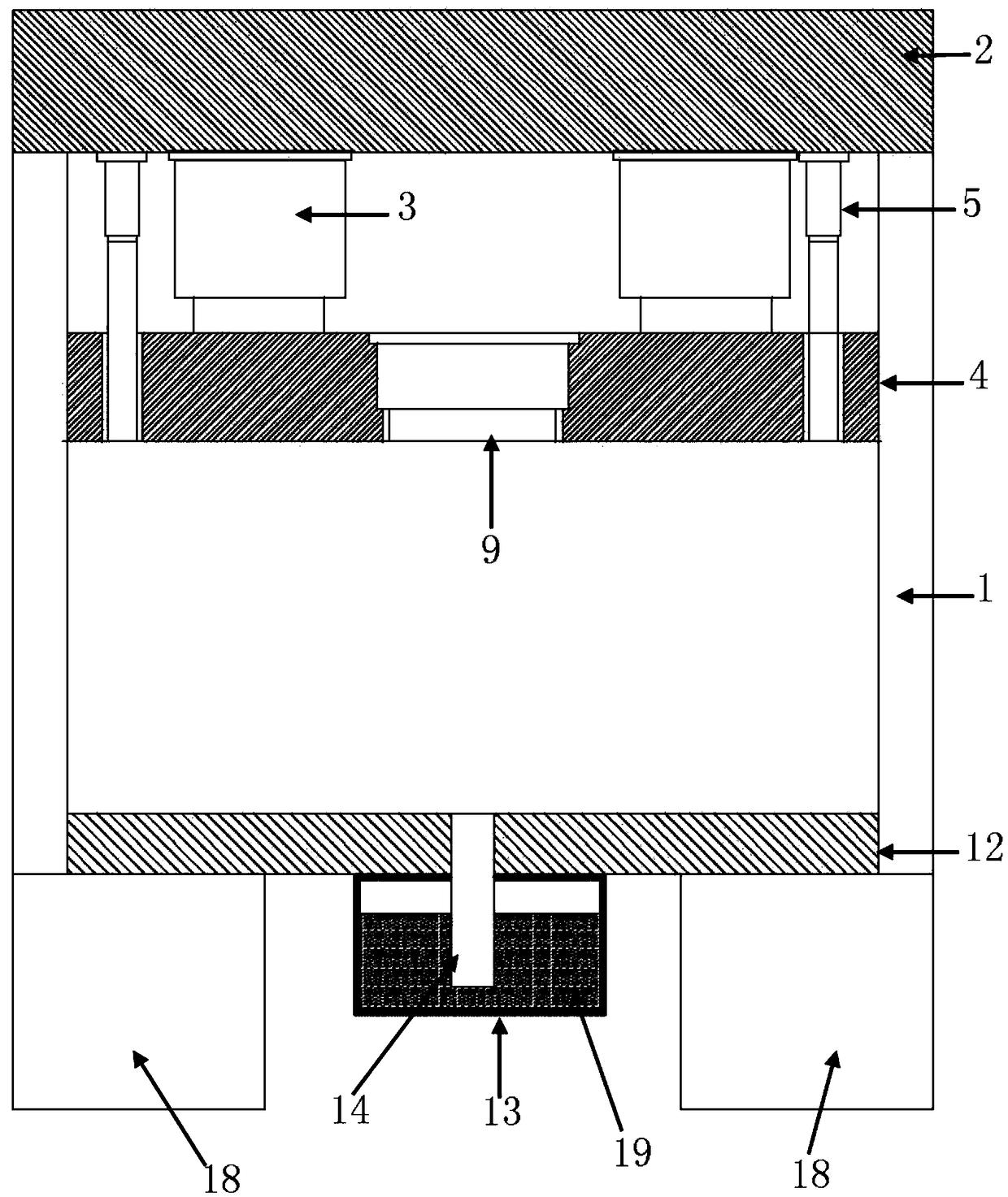
[0035] Such as Figure 1 to Figure 3 As shown, Embodiment 1 of the present invention provides a composite liquid forging device for the blank of the battery bottom case of an electric vehicle, including a frame 1, a top beam 2 is arranged above the frame 1, and the bottom of the top beam 2 is fixed A master cylinder 3 is connected, and a movable beam 4 is connected to the lower end of the master cylinder 3 .

[0036] The expansion and contraction of the main cylinder 3 can drive the movable crossbeam 4 to move up and down.

[0037]The periphery of the master cylinder 3 is provided with a mold clamping cylinder 5, the upper end of the mold clamping cylinder 5 is fixed on the top beam 2, and the piston rod of the mold clamping cylinder 5 passes through the movable beam 4 and is connected with a joint template6. The mold clamping cylinder 5 can drive the clamping plate 6 to move up and down.

[0038] The lower part of the movable beam 4 is connected with a main pressure head 1...

Embodiment 2

[0046] Such as Figure 2 to Figure 3 As shown, Embodiment 2 of the present invention provides a composite liquid die forging method for a blank of an electric vehicle battery bottom case, the method comprising the following steps:

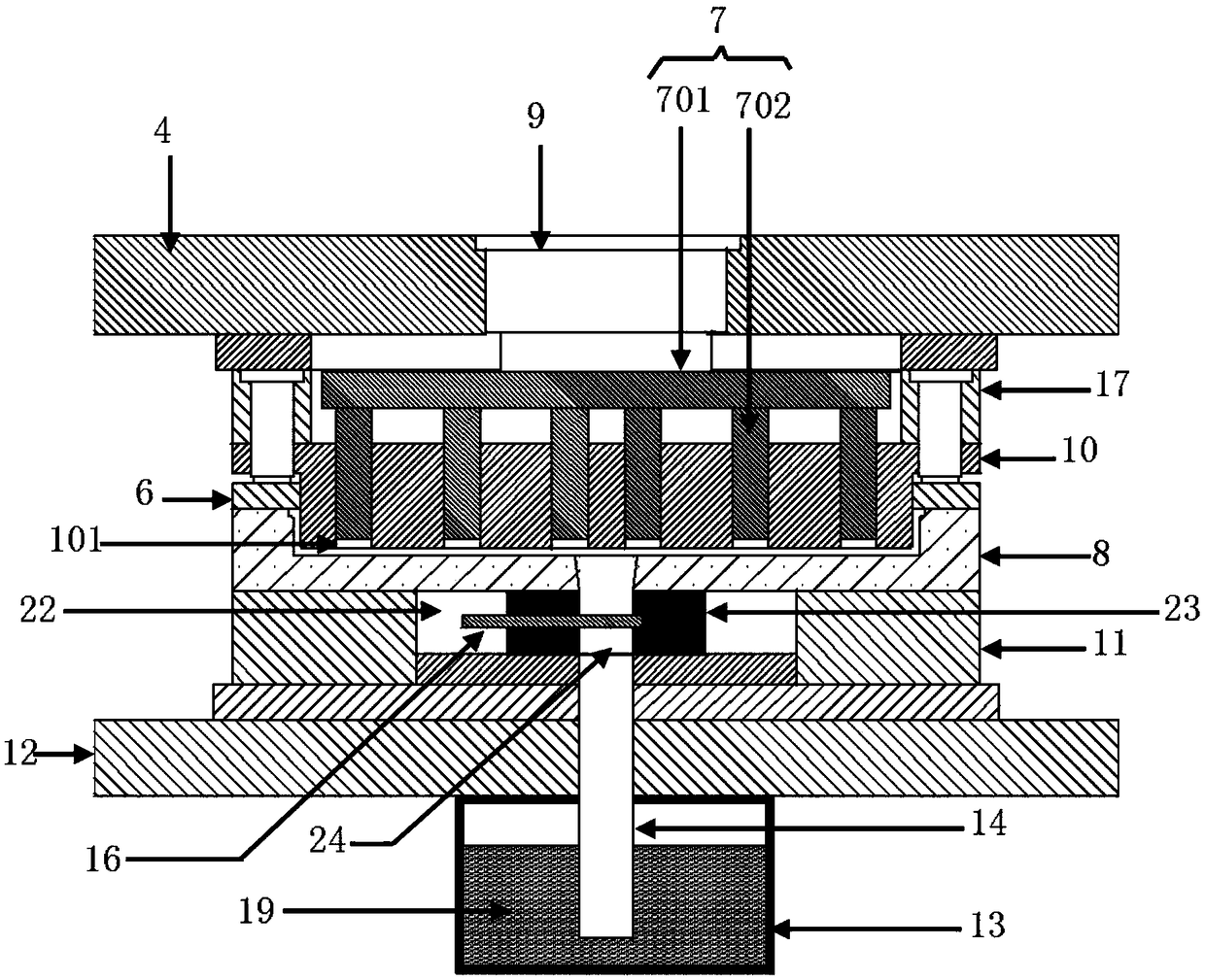
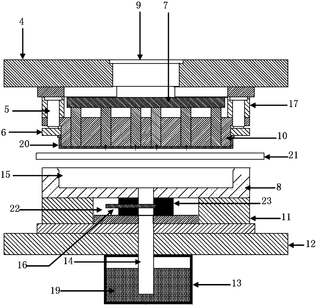
[0047] Step S110: Clamping the mold: push the movable beam 4 downward through the main cylinder 3, so that the main pressure head 10 extends into the mold cavity 15 to reach the predetermined position, and the mold clamping cylinder 5 continues to move downward so that the clamping plate 6 is attached to the upper edge of the mold 8 and pressurized until the set pressure is still; the auxiliary pressure head 7 moves to the preset position under the drive of the feeding cylinder 9, and the horizontal inserting plate 16 in the connecting block 23 is pulled apart by the hydraulic cylinder;

[0048] Step S120: Mold filling: open the air valve of the holding furnace 13 to pressurize the aluminum alloy liquid 19 in the holding furnace 13, so that the alu...

Embodiment 3

[0058] Such as Figure 2 to Figure 3 As shown, the third embodiment of the present invention provides a composite liquid die forging device for the blank of the battery bottom case of an electric vehicle and a method for using the device for die forging.

[0059] The liquid forging position of the liquid die forging for the blank of the electric vehicle battery bottom case is the horizontal position, and the opening of the battery bottom case is upward; The head is pressurized from top to bottom to form a shell cavity, and the position of the boss is partially pressurized and fed.

[0060] The device used for the liquid die forging of the blank of the electric vehicle battery bottom case includes four parts: the holding furnace, the pick-up mechanism of the liquid die forging machine and the mold:

[0061] The alloy liquid in the holding furnace enters the mold cavity through the liquid riser under the pressure of 0.2-0.4MPa;

[0062] The liquid die forging machine is a hydr...


PUM


Abstract

The invention provides a composite liquid die forging device and a method for a bottom shell workblank of an electric vehicle battery, belongs to the technical field of the automobile battery bottom shell forging technology. The device comprises a rack, the top of the rack is provided with a top beam, the top beam is connected with a main cylinder, the lower end of the main cylinder is connected with a movable cross-beam, the main cylinder is equipped with a clamping cylinder and the clamping cylinder is fixed on the top beam, and the piston rod of the clamping cylinder passes through the movable cross-beam to connect a template; the bottom of the movable beam is connected with a main head, and the lower part of the main head is provided with a die, the outer wall of the main head and theinner side wall of the template are connected in seal sliding connection mode; the movable cross-beam is equipped with a supplementary cylinder and the lower end of the supplementary cylinder is provided with an auxiliary pressure head; the die is located on a base, the base is located on a working platform; the bottom of the working platform is equipped with an incubator, the incubator is communicated to the die cavity of the die through a lift pipe. The battery shell is formed as a whole, without bubbles and impurities, and solidifies under the action of pressure, and the battery shell has the advantages of small and smooth microstructure high production efficiency and high material utilization rate.

Description

technical field [0001] The invention relates to the technical field of forging electric vehicle battery bottom shells, in particular to a compound liquid die forging device and method for blanks of electric vehicle battery bottom shells. Background technique [0002] The battery bottom case of an electric vehicle is a key part of a new energy vehicle. It is a boat-shaped shell in which a battery weighing 200-300kg is installed. There are many bosses on the bottom surface and many screw holes on the side wall. The outline size is about 1700mm in length, about 1200mm in width, about 120mm in height, and the horizontal projection area can reach 2m 2 , which is a large shell part, the precision molding of such a large shell part blank is very difficult. [0003] Because the outline size of the electric vehicle battery bottom case is too large, if it is formed by solid-state forging technology, the required equipment tonnage is more than 100MN, and the equipment investment is hu...

Claims


Application Information

Patent Timeline
Patent Type & Authority Applications(China)
IPC IPC(8): B22D18/04
CPCB22D18/04
Inventor 邢书明
Owner BEIJING JIAOTONG UNIV
Why Eureka
Try Eureka