Light guide plate and preparation method thereof

A light guide plate and light guide point technology, which is applied in the field of light guide plates, can solve problems such as uneven texture, large dispersion, and increased light energy loss, and achieve the effects of simple and fast installation and maintenance, no yellowing, and uniform light guide

Active Publication Date: 2020-06-23
KUNSHAN CHENGTAI ELECTRIC
View PDF5 Cites 0 Cited by
  • Summary
  • Abstract
  • Description
  • Claims
  • Application Information

AI Technical Summary

Problems solved by technology

However, due to the uneven distribution of the thickness of the light guide plate in the traditional light guide plate, the dispersion of the material in the light guide plate is large, the texture is uneven, and the toughness is poor during use, and the damage rate is high. The existing light guide plate cannot It makes the light refract, reflect and scatter well to play the role of soft light, and in the long-term use process, the light transmission performance will deteriorate, which will increase the loss of light energy, and the problem of light uniformity and light transmission cannot be well achieved.

Method used


Image

  • Light guide plate and preparation method thereof
  • Light guide plate and preparation method thereof
  • Light guide plate and preparation method thereof

Examples


Embodiment 1

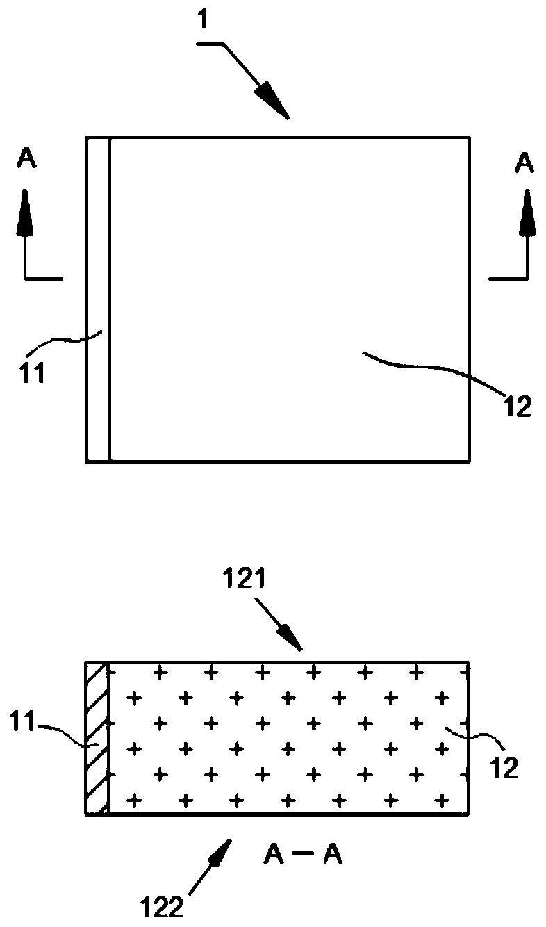
[0043] A light guide plate, the light guide plate 1 includes a light exit surface 122, a back surface 121, and several sides, the light exit surface 122 is arranged opposite to the back surface 121, the back surface 121 is provided with light guide points, and the sides are connected to the light exit surface 122 And the back side 121, wherein at least one side is provided with a light-introduction layer 11, the part 12 of the light guide plate other than the light-introduction layer is a PS layer, and the light-introduction layer material is composed of the following components in parts by weight: polyparaphenylene 25 parts of ethylene glycol diformate, 2 parts of superfine modified alumina, 10 parts of n-propyl silicate, 25 parts of hydroxypropyl methylcellulose, 10 parts of ultrafine active silica powder, 4 parts of simethicone , 8 parts of polyetherimide resin, 10 parts of sodium lauryl sulfate, 8 parts of vinyl methyl ether, 5 parts of ethylene bis stearic acid amide, 4 pa...

Embodiment 2

[0051] A light guide plate, the light guide plate 1 includes a light exit surface 122, a back surface 121, and several sides, the light exit surface 122 is arranged opposite to the back surface 121, the back surface 121 is provided with light guide points, and the sides are connected to the light exit surface 122 And the back side 121, wherein at least one side is provided with a light-introduction layer 11, the part 12 of the light guide plate other than the light-introduction layer is a PS layer, and the light-introduction layer material is composed of the following components in parts by weight: polyparaphenylene 28 parts of ethylene glycol diformate, 5 parts of superfine modified alumina, 12 parts of n-propyl silicate, 30 parts of hydroxypropyl methylcellulose, 11 parts of ultrafine active silica powder, 4 parts of simethicone , 9 parts of polyetherimide resin, 11 parts of sodium lauryl sulfate, 12 parts of vinyl methyl ether, 6 parts of ethylene bis stearic acid amide, 5 p...

Embodiment 3

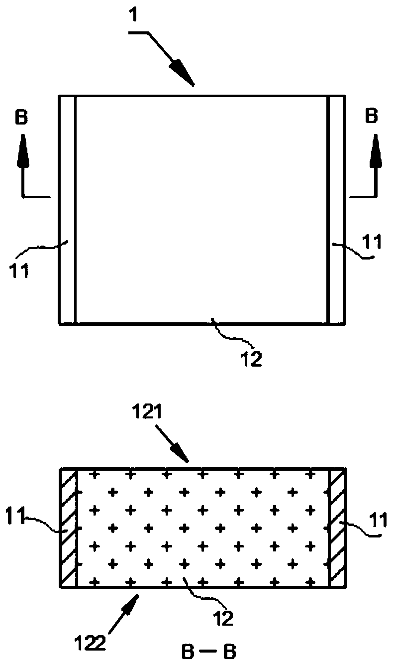
[0059] Using the materials of Example 2, the structure of the prepared light guide plate device is basically the same as that of Example 1, the difference is that the light guide plate 1 is a rectangular plate, and the two sides of the rectangular plate are provided with light-incoming layers 11; the two sides are opposite sides, such as image 3 shown.


PUM

PropertyMeasurementUnit
refractive indexaaaaaaaaaa

Abstract

The invention discloses a light guide plate and a preparation method thereof. The light guide plate includes a light emitting surface, a back surface and side surfaces; the light emitting surface is opposite to the back surface; the side surfaces are connected to the light emitting surface and the back surface, wherein at least one side surface is provided with a light incident layer; and a portion other than the light incident layer of the light guide plate is a PS layer. The light incident layer material is composed of the following parts by weight: polyethylene glycol terephthalate, ultrafine modified alumina, n-propyl silicate, hydroxypropyl methylcellulose, ultrafine active silicon micro-powder, dimethyl silicone oil, polyetherimide resin, lauryl sodium sulfate, vinyl methyl ether, ethylene bis stearic acid amide, stearate, dibutyl phthalate, hexamethyldisilane, thermoplastic polyurethane elastomer, calcium hydrogen phosphate, dioctyl ester, stabilizer and composite antioxidant; the light guide plate is prepared by mixing various components; and the light guide plate has strong stability and good light transmittance, and can reduce light loss.

Description

technical field [0001] The invention belongs to the technical field of light guide plates, and in particular relates to a light guide plate and a preparation method thereof. Background technique [0002] The light guide plate uses the optical-grade acrylic plate to absorb the light emitted from the lamp to stay on the surface of the optical-grade acrylic plate. When the light hits each light guide point, the reflected light will spread to all angles, and then destroy the reflection condition and be emitted from the front of the light guide plate. . Through light guide points of various densities and sizes, the light guide plate can be made to emit light evenly. [0003] The light panel design principle originates from the LCD screen of a laptop computer, and is a high-tech product that transforms a line light source into a surface light source. Optical-grade acrylic (PMMA) / PC is used as the base material, and the backlight module technology of LCD display and notebook comp...

Claims


Application Information

Patent Timeline
Patent Type & Authority Patents(China)
IPC IPC(8): G02B6/00C08L67/02C08L1/28C08L79/08C08L75/04C08L83/04C08K13/06C08K3/36C08K5/20C08K5/098C08K5/12C08K3/22
Inventor 盛玉林
Owner KUNSHAN CHENGTAI ELECTRIC
Why Eureka
Try Eureka