Eureka AIR delivers breakthrough ideas for toughest innovation challenges, trusted by R&D personnel around the world.

Laser-assisted micromachining system and temperature control method thereof

A laser-assisted and micro-machining technology, applied in the field of micro-machining, can solve the problems of affecting the size, reducing the machining accuracy and yield of the workpiece, and large fluctuations, achieving the effects of not easy dimensional deformation, avoiding excessive temperature, and improving machining accuracy.

Active Publication Date: 2018-11-16
RUITAI OPTICAL CHANGZHOU CO LTD
View PDF7 Cites 3 Cited by
  • Summary
  • Abstract
  • Description
  • Claims
  • Application Information

AI Technical Summary

Problems solved by technology

[0005] Laser heating has significantly improved the cutting performance of the material surface and is convenient for cutting, but there are still the following defects: with the increase of laser power and cutting speed, the heat on the surface of the tool material is easy to gather and conduct to the tool holder of the cutting workpiece , if the heat is not released in time, it will easily lead to large fluctuations in the surface temperature of the tool and tool holder, such as figure 1 shown
[0007] In view of the fact that the temperature of the tool module for cutting workpieces is unstable and fluctuates greatly, based on the principle of thermal expansion and contraction, the size of the tool and tool holder changes with the change of temperature, which affects the size of the workpiece during processing and reduces the Workpiece machining accuracy and yield

Method used


Image

  • Laser-assisted micromachining system and temperature control method thereof
  • Laser-assisted micromachining system and temperature control method thereof
  • Laser-assisted micromachining system and temperature control method thereof

Examples


Embodiment Construction

[0040] The present invention will be further described below in conjunction with the accompanying drawings and embodiments.

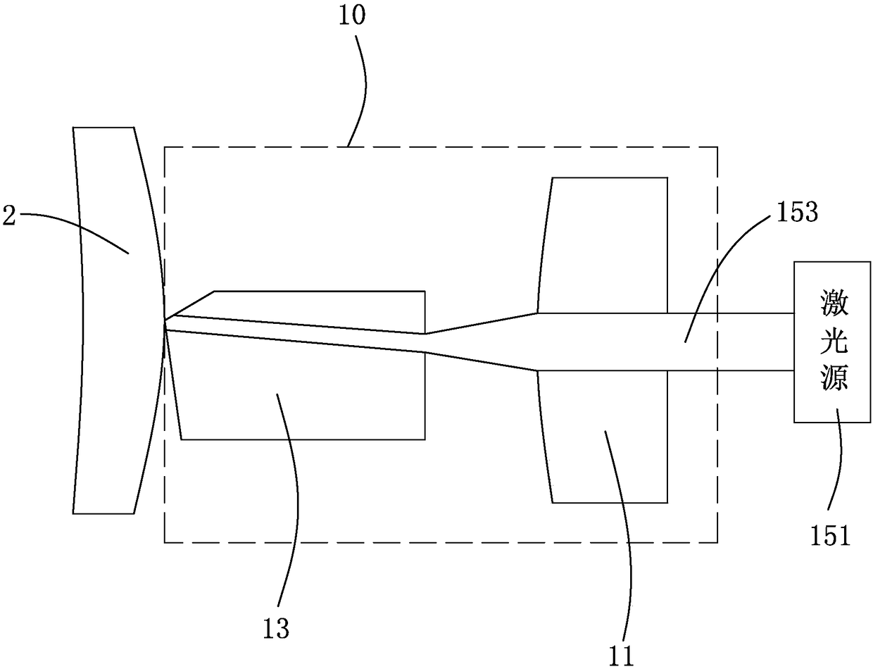
[0041] see figure 2 , is a schematic diagram of the principle of the laser-assisted micromachining system provided by the present invention. The laser-assisted micromachining system 10 cuts the workpiece 2 to be processed. The laser-assisted micromachining system 10 provides a laser beam to heat the workpiece 2 to be processed, and through reasonable control of the laser power, the size and speed of the spot pair, the laser beam generated by it is irradiated to the tool module 13 through focusing ( refer to Figure 5 ) of the front end, the workpiece 2 to be processed is irradiated and heated to change the mechanical properties of the material and reduce the cutting force.

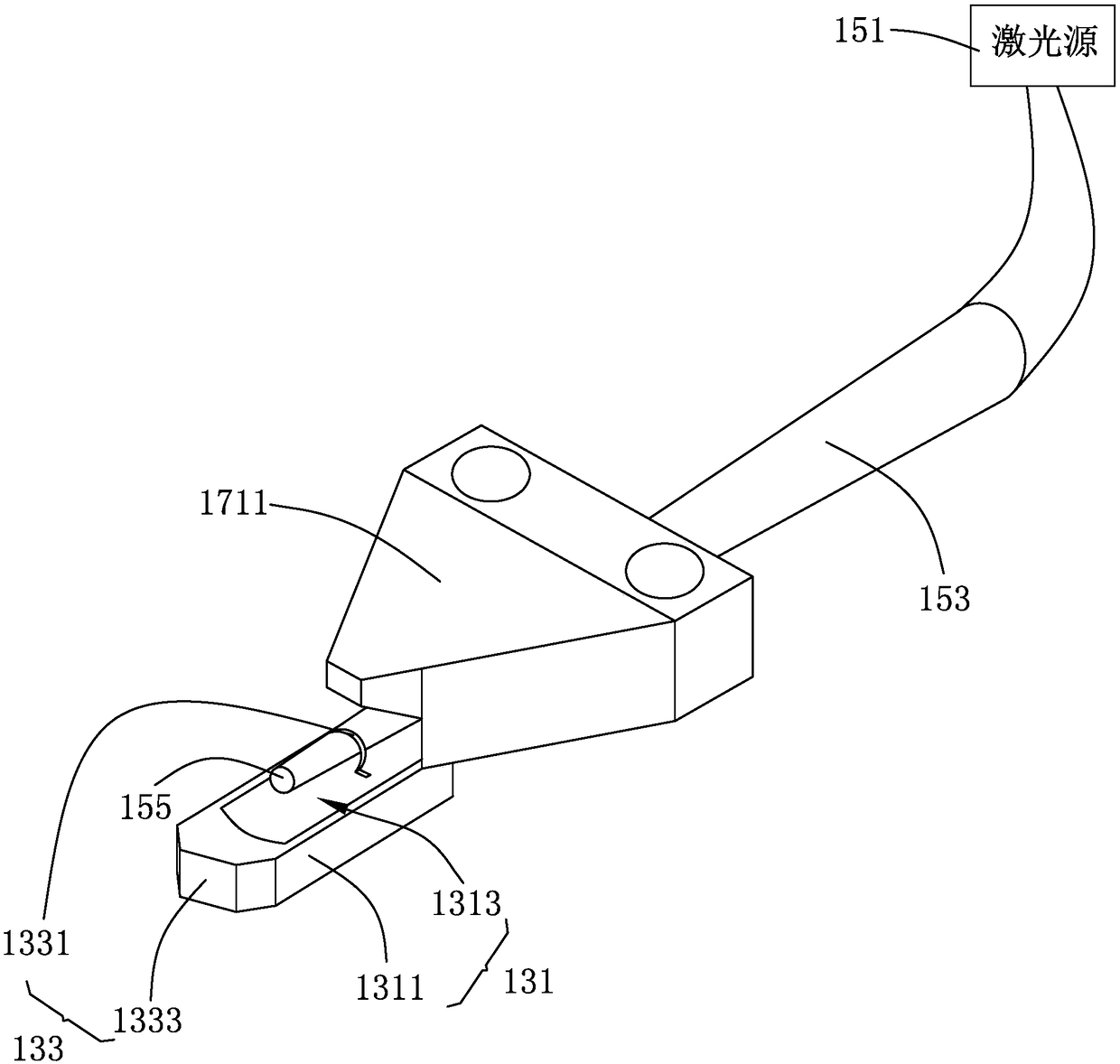
[0042] Please refer to image 3 and Figure 4 ,in image 3 It is a structural schematic diagram of the laser-assisted micromachining system of the present invention, Figure...


PUM


Abstract

The invention discloses a laser-assisted micromachining system. The system comprises a work slide table, a tool module used for cutting a to-be-machined workpiece, a laser module and a temperature control module. The laser module is arranged on the work slide table and used for heating the to-be-machined workpiece as the work slide table moves in a three-dimensional space. The temperature controlmodule comprises temperature inductors, a cooler, a controller and a coolant. The temperature inductors induct the real-time temperature values of the cooler, the cooler is arranged on the work slidetable and supports the tool module, the controller feeds a control signal back to control the working state of the cooler according to the temperature values inducted by the temperature inductors, andthe coolant is used for controlling the temperatures of the cooler to be distributed within a set range. Meanwhile, the invention further provides a temperature control method of the laser-assisted micromachining system. According to the laser-assisted micromachining system and the temperature control method thereof, heat accumulation is avoided, the machining precision is improved, and the product yield is increased.

Description

【Technical field】 [0001] The invention relates to the technical field of micromachining, in particular to a laser-assisted micromachining system and a temperature control method using the micromachining system. 【Background technique】 [0002] Difficult-to-machine materials such as alloy steel and fiber-reinforced metal composites have excellent properties and have been applied to the processing and manufacturing of micro-sized structures and workpieces. During the cutting process of difficult-to-machine materials, due to their high strength and high hardness, some feature accuracy and cutting speed are limited by the rigidity of the machine tool and the strength and rigidity of ordinary micro-tools, and the rapid wear of the tool will lead to the machining accuracy of small parts. reduce. Therefore, it is necessary to use effective methods to process tiny parts. [0003] Laser-assisted micro-machining is a composite processing method that focuses the laser beam on the surf...

Claims


Application Information

Patent Timeline
IPC IPC(8): B23Q11/00B23Q11/10
CPCB23Q11/00B23Q11/10B23K26/0093B23P25/006B23K26/703B23K2103/52B23K26/032B23K26/034B23K31/10B23K26/064
Inventor 尼尔斯·克里斯蒂安·罗默·霍姆朱秉科
Owner RUITAI OPTICAL CHANGZHOU CO LTD
Why Eureka
Eureka Blog
Learn More