Typical path planning method for 3D (three-dimensional) printing of continuous fiber reinforced composites

A reinforced composite material and continuous fiber technology, which is applied in additive processing, manufacturing auxiliary devices, processing data acquisition/processing, etc., can solve the problems of printing failure of forming components, restricting the performance of forming components, and weak fiber binding force, etc. The effect of overall performance, reduction of molding defects, and improvement of bonding force

Active Publication Date: 2018-11-27
DALIAN UNIV OF TECH
View PDF4 Cites 28 Cited by
  • Summary
  • Abstract
  • Description
  • Claims
  • Application Information

AI Technical Summary

Problems solved by technology

[0005] The purpose of the present invention is to overcome the defects of the prior art. For the path planning of continuous fiber 3D printing, there are still problems such as weak fiber bonding force at bends, easy fiber breakage at small-angle bends, and many path breakpoints. Causes the formation of defects in continuous fiber composite molding components, severely restricts the performance of molding components, and even leads to printing failures of molding components

Method used


Image

  • Typical path planning method for 3D (three-dimensional) printing of continuous fiber reinforced composites
  • Typical path planning method for 3D (three-dimensional) printing of continuous fiber reinforced composites
  • Typical path planning method for 3D (three-dimensional) printing of continuous fiber reinforced composites

Examples


Embodiment Construction

[0025] The present invention will be further described in detail below in conjunction with the accompanying drawings and technical solutions.

[0026] The continuous fiber reinforced material used in the planning method of the present invention is one or more of continuous carbon fiber wire, continuous glass fiber wire, continuous ceramic fiber or continuous silicon carbide fiber, and also includes continuous fiber tow prepared according to special application occasions; the resin used It is one or more of ABS resin, polyamide or polyetheretherketone thermoplastic resin.

[0027] In this embodiment, 1K continuous carbon fiber and nylon are used as raw materials for 3D printing, wherein the continuous carbon fiber is pretreated, and according to the experiment, the minimum angle that can be bent is 13°.

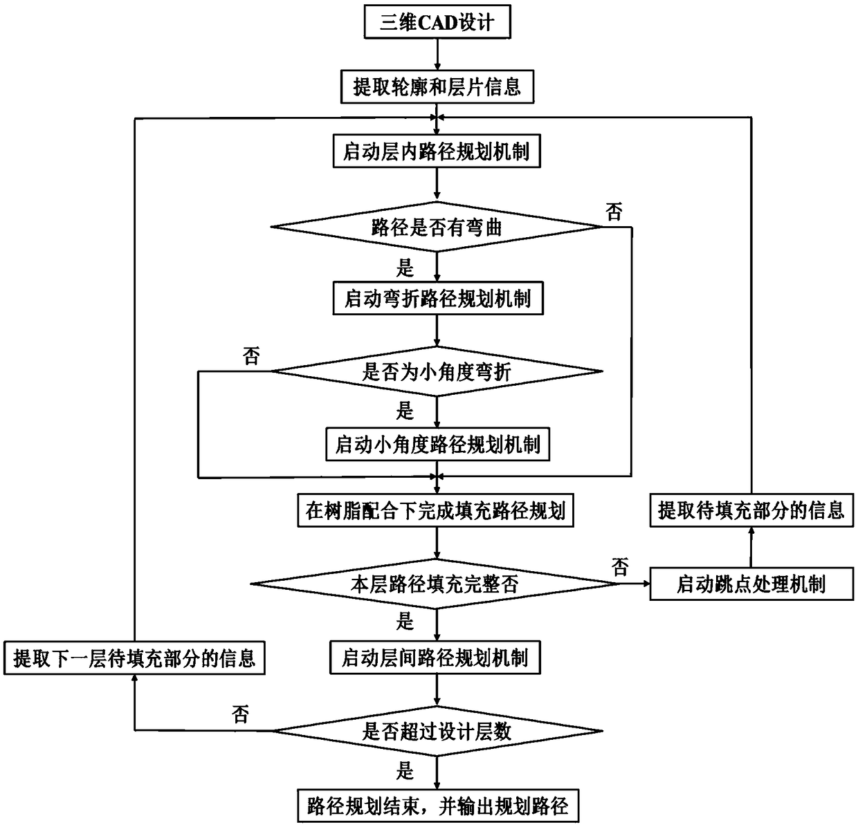
[0028] The flow chart of the path planning method in this embodiment is as follows figure 1 As shown, the specific steps of the planning method are as follows:

[0029]Step ...


PUM


Abstract

The invention discloses a typical path planning method for 3D (three-dimensional) printing of continuous fiber reinforced composites and belongs to the field of rapid prototyping of the composites. Inthe method, a three-dimensional model is built by using CAD (computer aided design) modeling software according to actual size requirements of forming components and is subjected to slice stratification by the aid of the three-dimensional software to acquire profile and slice information; the degree of path bending is judged and corresponding path planning mechanisms are started, and with the help of the jump point processing mechanism, jump points can be accurately located and the action of the jump points is completed; fiber interlayer conversion without breakpoint is realized by using an interlayer path planning mechanism, and high quality and high efficiency three-dimensional printing new path of the continuous fiber reinforced composites is realized. In the method, the printing pathwith the least breakpoints is planned out, and mechanical property of the continuous fiber reinforced composites is guaranteed; forming defects in the bending of continuous fiber are effectively reduced, binding force of the continuous fiber in the bending is improved, and integral performance of the forming components is improved.

Description

technical field [0001] The invention belongs to the field of rapid prototyping of composite materials, and relates to a planning method for a typical path of 3D printing of continuous fiber reinforced composite materials. Background technique [0002] Fiber-reinforced composite materials have the advantages of light weight, high strength, and can be designed and manufactured as a whole, and have now become the material of choice for key components in high-end equipment fields such as aviation and aerospace. However, as the functional and high-performance requirements of key components in high-end equipment continue to increase, the structural design of components becomes more and more complex. The traditional lay-up and solidification manufacturing process cannot meet the shape requirements of complex components, which seriously affects the fiber composite materials. Application in complex structural parts of high-end equipment. [0003] 3D printing technology applies the i...

Claims


Application Information

Patent Timeline
Patent Type & Authority Applications(China)
IPC IPC(8): B29C64/386B33Y50/00
CPCB29C64/386B33Y50/00
Inventor 王福吉王公硕张中标成德王琦
Owner DALIAN UNIV OF TECH
Why Eureka
Try Eureka