
Waste water collection and recycling device for industrial metallurgy

A waste water collection and industrial technology, applied in the direction of metallurgical waste water treatment, use of liquid separation agent, heating water/sewage treatment, etc., can solve the problems of insufficient energy saving and environmental protection, complex and changeable water quality, large water volume, etc., to improve efficiency and save water resource effect

Inactive Publication Date: 2018-11-30
王菲
View PDF0 Cites 2 Cited by
  • Summary
  • Abstract
  • Description
  • Claims
  • Application Information

AI Technical Summary

Problems solved by technology

Metallurgical industrial wastewater refers to the wastewater discharged from the production process of the metallurgical industry. It is characterized by a large amount of water, many types, and complex and changeable water quality. According to the source and characteristics of the wastewater, it mainly includes cooling water, pickling wastewater, dust removal wastewater and gas, Washing slag water, coking wastewater, the current industrial metallurgical wastewater recycling device has the problem of insufficient energy saving and environmental protection

Method used


Image

  • Waste water collection and recycling device for industrial metallurgy
  • Waste water collection and recycling device for industrial metallurgy
  • Waste water collection and recycling device for industrial metallurgy

Examples


Embodiment Construction

[0024] The following will clearly and completely describe the technical solutions in the embodiments of the present invention with reference to the accompanying drawings in the embodiments of the present invention. Obviously, the described embodiments are only some of the embodiments of the present invention, not all of them.

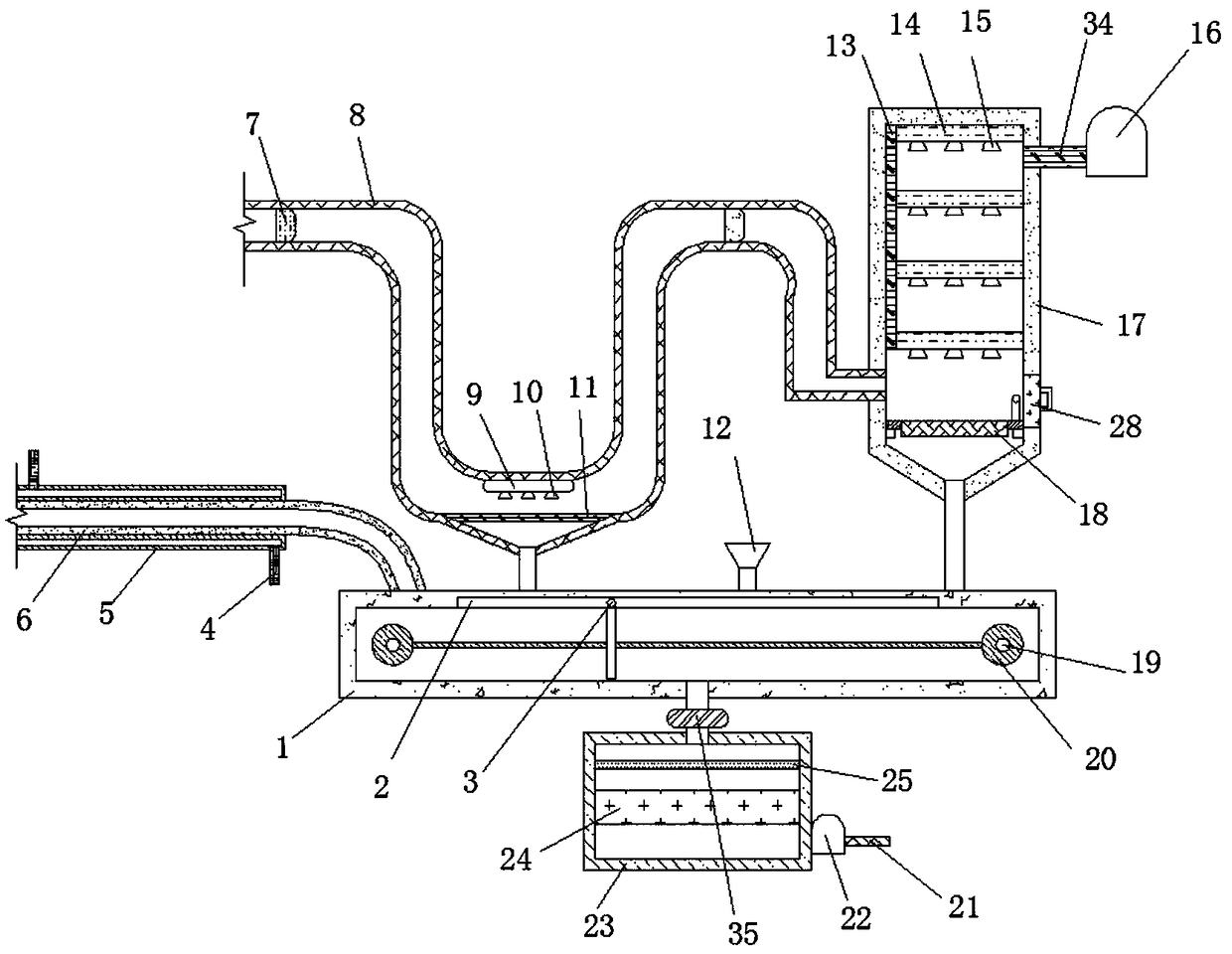
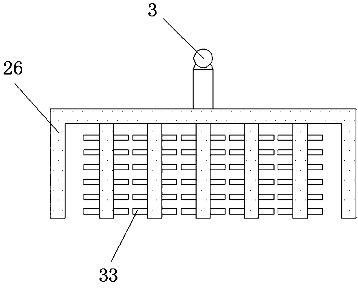
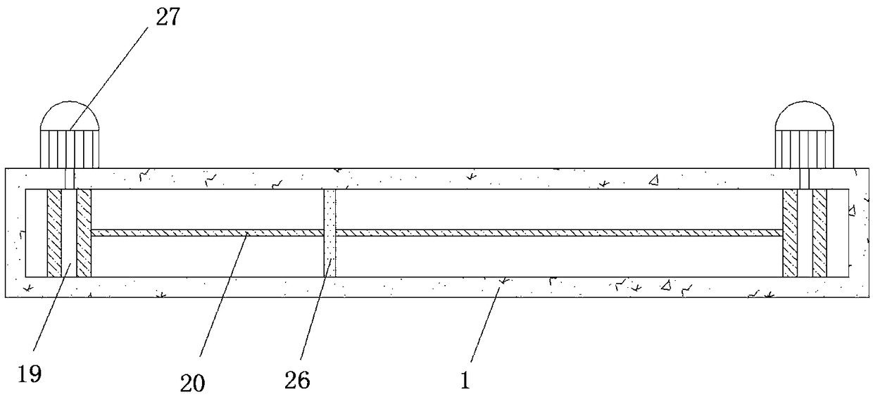
[0025] refer to Figure 1-5 , an industrial metallurgical waste water collection and recycling device, comprising a sedimentation tank 1, a waste water pipe 6 is plugged into one end of the top outer wall of the sedimentation tank 1, and a cooling water pipe 5 is sleeved on the outer wall of the waste water pipe 6 away from the sedimentation tank 1 at one end A clamping cavity is provided between the inner wall of the cooling water pipe 5 and the outer wall of the circumference, and the two ends of the outer wall of the clamping cavity are plugged with water pipes 4, and the middle position of the outer wall of the top of the sedimentation tank 1 is plug...


PUM


Abstract

The invention belongs to the technical field of industrial metallurgy, and in particular, relates to a waste water collection and recycling device for industrial metallurgy. In view of the problems ofsimple design structure, insufficient energy saving and environmental protection, and low coagulation and sedimentation efficiency, provided is the waste water collection and recycling device including a sedimentation tank; a waste water pipe is inserted at one end of the outer wall of the top of the sedimentation tank; a cooling water pipe sleeves one end, away from the sedimentation tank, of the circumferential outer wall of the waste water pipe; a clamping cavity is arranged between the circumferential inner wall and the circumferential outer wall of the cooling water pipe, and both ends of the circumferential outer wall of the clamping cavity are each connected with a water pipe in an inserted manner; the middle position of the outer wall of the top of the sedimentation tank is connected with a first connecting pipe in an inserted manner, and one end, away from the sedimentation tank, of the first connecting pipe is connected with a smoke exhaust pipe by a fastening bolt. Waste water and a coagulant in the sedimentation tank are fully mixed, the coagulation sedimentation efficiency is improved, the mixture is conveyed to a water outlet pipe and a main water pipe for recyclingutilization through a water pump and a circulating water pipe, water resources is are saved, waste heat of the waste water is reused, and energy saving and environmental protection are realized.

Description

technical field [0001] The invention relates to the technical field of industrial metallurgy, in particular to a device for collecting and recycling wastewater used in industrial metallurgy. Background technique [0002] Metallurgical industry refers to the industrial sector that mines, selects and sinters metal ores, smelts them, and processes them into metal materials. It is divided into: ferrous metallurgical industry, that is, the industrial sector that produces iron, chromium, manganese and their alloys. Modern industry, transportation, infrastructure and military equipment provide raw materials; non-ferrous metallurgical industry, that is, the metal refining industry sector that produces non-ferrous metals, such as copper smelting industry, aluminum industry, lead-zinc industry, nickel-cobalt industry, tin smelting industry , precious metal industry, rare metal industry and other sectors. Metallurgical industrial wastewater refers to the wastewater discharged from the...

Claims


Application Information

Patent Timeline
Patent Type & Authority Applications(China)
IPC IPC(8): C02F9/04C02F9/10B01D47/06B01D53/18C02F103/16
CPCC02F9/00B01D47/06B01D53/18C02F1/001C02F1/02C02F1/52C02F2001/007C02F2103/16
Inventor 王菲
Owner 王菲
Learn More