Waste heat recovery device for bottom slag of circulating fluidized bed boiler

A circulating fluidized bed and recovery device technology, which is applied to fluidized bed combustion equipment, lighting and heating equipment, and fuel burned in a molten state, can solve the problems of large flow resistance, large air volume consumption, and burning coking, etc., and achieve extended The effect of contact time, low smoke flow rate and high reliability

Inactive Publication Date: 2018-12-11
CHONGQING UNIV
View PDF7 Cites 3 Cited by
  • Summary
  • Abstract
  • Description
  • Claims
  • Application Information

AI Technical Summary

Problems solved by technology

After the fluidized air of the fluidized bed slag cooler absorbs heat in the fluidized bed slag cooler, the hot air formed at about 300-400°C is sent back to the furnace as supplementary secondary air, but in actual operation there are gas-solid The contradiction between heat exchange and heating surface wear, as well as common problems such as slag blocking and burning coking; although the above problems have been solved to a certain extent by using a double-separation fluidized bed slag cooler (CN201010297379.9), the air in The air temperature after heat exchange in the slag cooler does not exceed 400°C, and the air volume consumption is large
The common problem of th

Method used


Image

  • Waste heat recovery device for bottom slag of circulating fluidized bed boiler
  • Waste heat recovery device for bottom slag of circulating fluidized bed boiler
  • Waste heat recovery device for bottom slag of circulating fluidized bed boiler

Examples


Embodiment

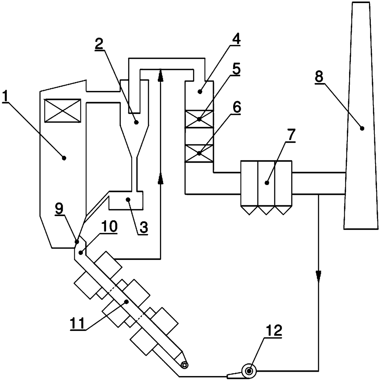
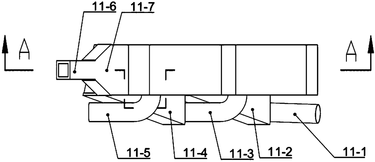
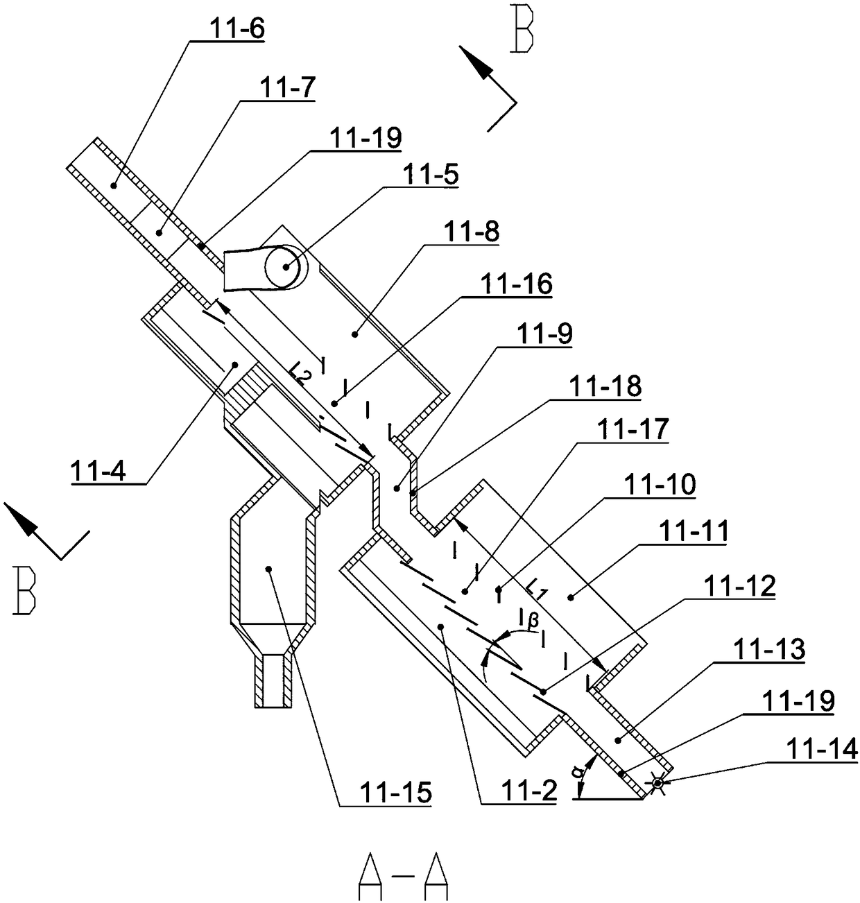
[0017] The structure of a circulating fluidized bed boiler bottom slag waste heat recovery device involved in this embodiment is as follows: Figure 1-Figure 4 As shown, the device mainly includes a slag discharge pipe 9 and an inclined moving bed heat exchanger 11; wherein the inclined moving bed heat exchanger 11 includes 11-1 as the flue inlet section and 11-2 as the lower air chamber of the lower cross-flow section , 11-3 is the air chamber connected to the smoke pipe, 11-4 is the lower air chamber of the upper cross-flow section, 11-5 is the flue outlet section, 11-6 is the ash passage inlet section, 11-7 is the bottom slag diffusion section, 11 -8 is the upper air chamber in the upper cross-flow section, 11-9 is the sealing pressure section in the middle of the gray passage, 11-10 is the upper deflector, 11-11 is the upper air chamber in the lower cross-flow section, 11-12 is the lower deflector, 11-13 is the sealing pressure section at the lower part of the ash channel,...


PUM


Abstract

The invention discloses a waste heat recovery device for bottom slag of a circulating fluidized bed boiler. The waste heat recovery device comprises a slag discharging pipe (9) and an inclined movingbed heat exchanger (11) and is characterized in that the inclined moving bed heat exchanger (11) is integrally in an inclined form, each of an upper cross-flow section (11-16) and a lower cross-flow section (11-17) is composed of upper flow guide plates (11-10) and lower flow guide plates (11-12) and is provided with an upper air chamber and a lower air chamber, the upper air chamber (11-11) of the lower cross-flow section and the lower air chamber (11-4) of the upper cross-flow section are connected through an air chamber connecting smoke pipe (11-3), the lower air chamber (11-4) of the uppercross-flow section is provided with a bottom slag collecting box (11-15), an ash channel middle sealing and pressing section (11-9) is arranged between the two cross-flow sections, and an ash channellower sealing and pressing section (11-13) is arranged below the lower cross-flow section (11-17). According to the waste heat recovery device, recycled flue gas is adopted as a heat exchange medium,most of the heat of the bottom slag is recycled to the proper position of a hearth (1) or a tail flue (4), and therefore the physical heat loss of boiler ash is reduced, and the boiler efficiency isimproved.

Description

Technical field: [0001] The invention belongs to the technical field of circulating fluidized bed boilers, in particular to a device for cooling high-temperature bottom slag and recovering waste heat of circulating fluidized bed boilers. Background technique: [0002] The high-temperature bottom slag discharged from the circulating fluidized bed boiler contains a large amount of physical sensible heat, and it is necessary to use a suitable bottom slag cooling device for bottom slag cooling and waste heat recovery. Traditional bottom slag waste heat technologies include drum water cooling, fluidized bed air cooling, moving bed air cooling, etc. None of these traditional methods can obtain high-temperature heat exchange medium (water or air), and the waste heat utilization rate is low, accompanied by problems such as large resistance and wear. The outlet water temperature of the drum slag cooler is below 100°C, and the recovery rate of waste heat from the bottom slag is only ...

Claims


Application Information

Patent Timeline
IPC IPC(8): F23C10/24
CPCF23C10/24
Inventor 卢啸风杨帆郑雄李建波王泉海范旭宸刘卓
Owner CHONGQING UNIV
Why Eureka
Try Eureka