
Accumulator piezoelectric injector with variable injection rule

A fuel injection regular, pressure-accumulating technology, applied in the direction of machines/engines, fuel injection devices, engine components, etc., can solve problems such as fuel leakage from injectors, slow response speed of needle valve seating, and impact on fuel utilization

Inactive Publication Date: 2018-12-18
HARBIN ENG UNIV
View PDF4 Cites 1 Cited by
  • Summary
  • Abstract
  • Description
  • Claims
  • Application Information

AI Technical Summary

Problems solved by technology

Although the electromagnetic control injector has improved the emission performance of the diesel engine, there are still some shortcomings: the injector usually adopts the form of single-way oil inlet, and the response speed of the needle valve seat is slow, and due to the balance of the diameter of the inlet and outlet holes relationship, it is difficult to further improve the response characteristics; the dynamic oil return in the form of a two-position two-way valve is large, which affects fuel utilization; the axial gap between the needle valve and the control plunger causes static leakage in the injector Fuel problem; due to the inductance of the solenoid valve coil, there is a certain lag time in its response, which leads to further increase in the number of fuel injections is limited, and the repeatability of fuel injection needs to be improved; in the state of large fuel injection, the fuel injection of each cylinder Process uniformity and stability decline, etc.

Method used


Image

  • Accumulator piezoelectric injector with variable injection rule
  • Accumulator piezoelectric injector with variable injection rule
  • Accumulator piezoelectric injector with variable injection rule

Examples


Embodiment Construction

[0023] The present invention will be described in more detail below in conjunction with the accompanying drawings:

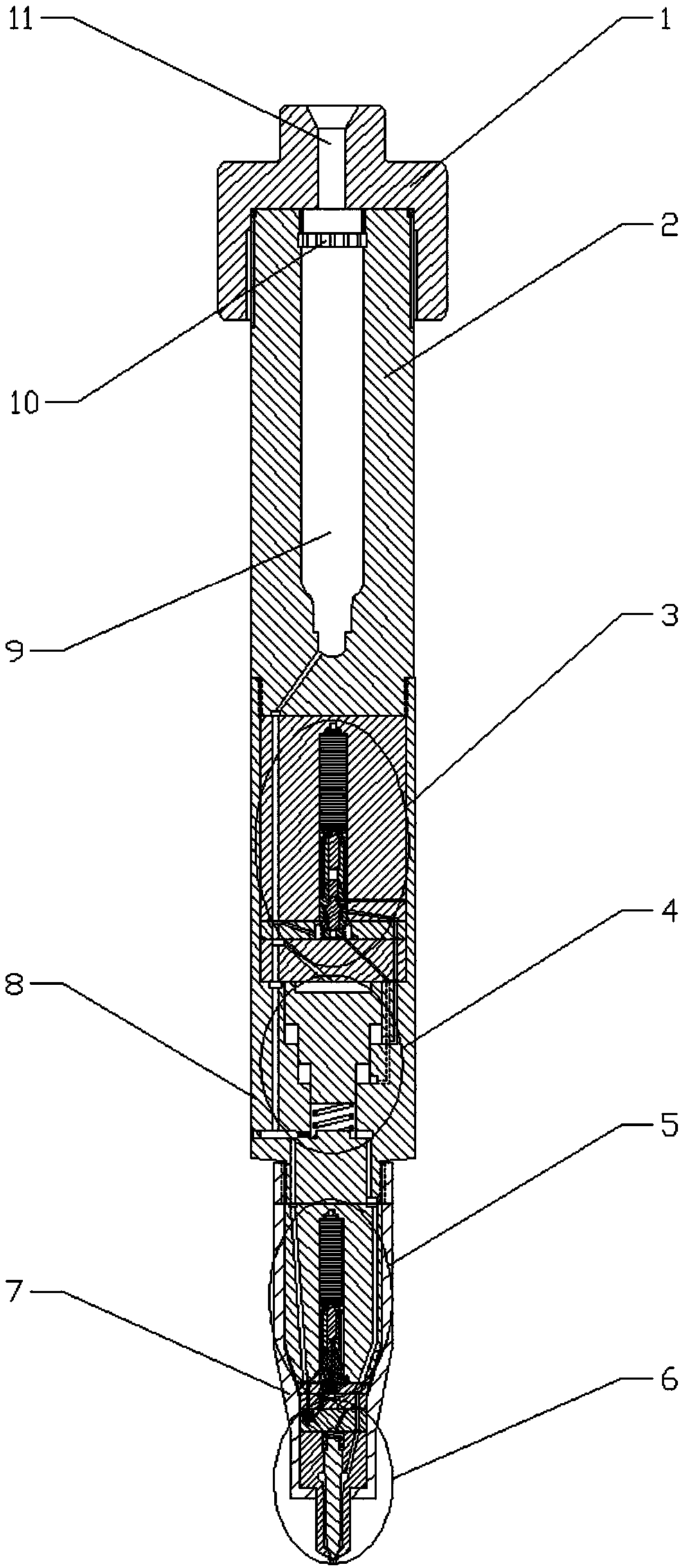
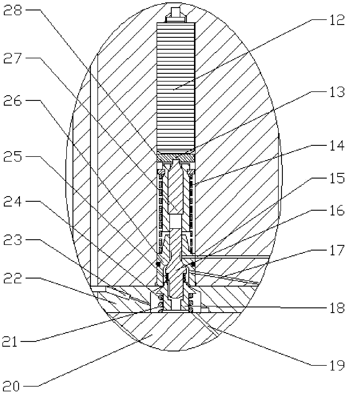
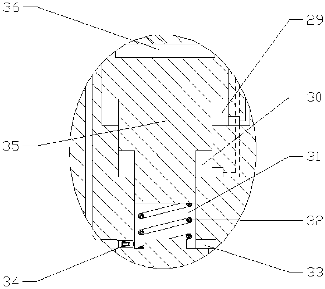
[0024] combine Figure 1-6 , the present invention is a pressure accumulating piezoelectric injector with variable fuel injection law, which is composed of a fastening cap 1, a pressure accumulating cavity wall 2, a pressure boosting control valve part 3, a three-stage piston assembly 4, an injection control valve part 5. The needle valve part 6, the injector body 8, the pressure accumulating chamber 9 and the filter orifice 10 are composed. The said booster control valve part 3 is mainly composed of a piezoelectric stack 12, a gasket 13, a plate spring 14, a booster control valve stem 16, a mushroom-shaped sleeve 18, a mushroom-shaped sleeve limiting orifice 22, and a bacteria-shaped sleeve. It is composed of a cylindrical sleeve spring 24 , a booster control valve stem spring 25 , a booster control valve stem sleeve 26 , a hydraulic core 27 and a hydraulic sl...


PUM


Abstract

The invention aims to provide an accumulator piezoelectric injector with a variable injection rule. The accumulator piezoelectric injector with the variable injection rule comprises a pressurized control valve part, a three-stage piston assembly, an injection control valve part, and a needle valve part. The accumulator piezoelectric injector with the variable injection rule adopts a pressurized control valve structure to control the pressurized area of a three-stage piston, different pressurized ratios can be effectively achieved, thus the injection rule is more flexible. The operating processof a needle valve is driven by a piezoelectric reactor, the response speed of the needle valve is high, the freedom degree of controlling is large, and the injection rule is flexible and controllable, thus the power performance and fuel economy of a diesel engine are effectively improved, and more stringent emission regulations can be met through the diesel engine; in addition, pressure fluctuation caused by fuel injection can be slowed down by a pressure accumulation cavity, accurate control of the fuel-injection quantity is facilitated, and especially for the control accuracy of small amount of oil can be significantly improved; and the pressure stabilizing effect of the pressure accumulation cavity reduces the size of a common rail pipe, thus the service life of the common rail pipe isprolonged.

Description

technical field [0001] The invention relates to a diesel engine, in particular to a diesel engine fuel system. Background technique [0002] The mechanical fuel injector is restricted by the cam of the high pressure fuel supply pump due to the fuel injection characteristics such as fuel injection timing, fuel injection pressure and fuel injection rate. With the increasingly stringent emission regulations, it is difficult to further improve the economy and emission performance of the engine. [0003] Compared with the mechanical fuel injector, the electromagnetically controlled fuel injector applied to the diesel electronically controlled fuel injection system has a faster response speed, flexible and controllable fuel injection characteristics, and more precise control of the fuel injection quantity. Although the electromagnetically controlled fuel injector has improved the emission performance of the diesel engine, it also has some shortcomings: the fuel injector usually a...

Claims


Application Information

Patent Timeline
IPC IPC(8): F02M47/02F02M63/00F02M61/10F02M61/20
CPCF02M47/027F02M61/10F02M61/20F02M63/0026
Inventor 白云付立洲蒋顺豪范立云
Owner HARBIN ENG UNIV
Learn More