
Efficient biomass conversion method

A biomass and high-efficiency technology, applied in the fields of biofuels, waste fuels, chemical recycling, etc., can solve the problems of waste of resources and insufficient utilization of heat, save energy, prevent waste of resources, and ensure the effect of reaction efficiency.

Active Publication Date: 2018-12-21
CHINA UNIV OF PETROLEUM (EAST CHINA)
View PDF6 Cites 4 Cited by
  • Summary
  • Abstract
  • Description
  • Claims
  • Application Information

AI Technical Summary

Problems solved by technology

While realizing the production of gasoline and diesel by lightening heavy oil, the generated coke is attached to the catalyst, and the catalyst activity can only be restored by burning. The large amount of heat generated by burning can not be fully utilized, resulting in waste of resources.

Method used


Image

  • Efficient biomass conversion method
  • Efficient biomass conversion method
  • Efficient biomass conversion method

Examples


Embodiment 1

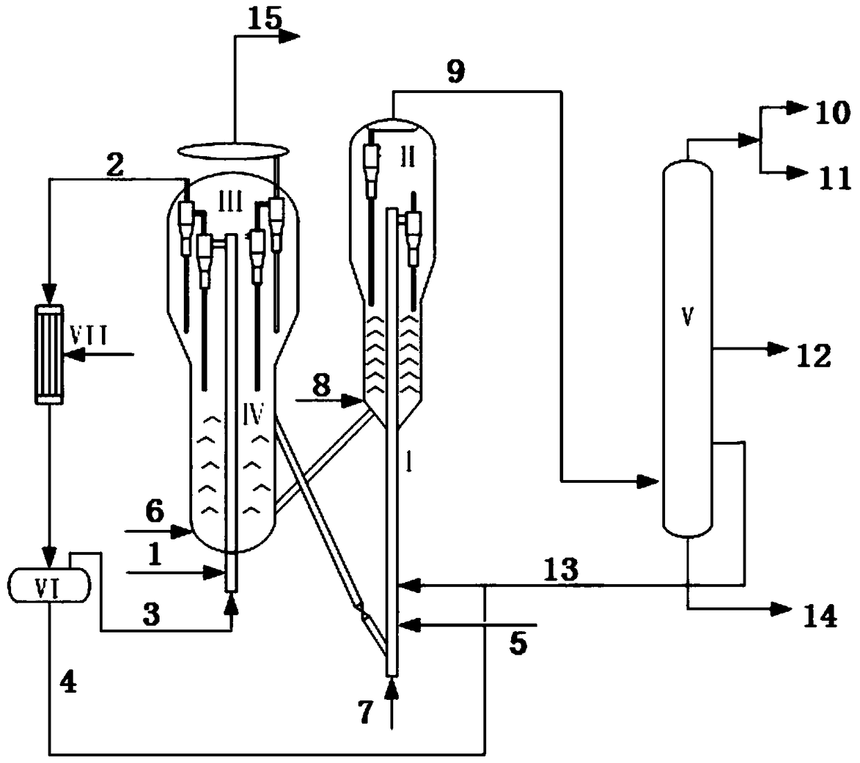
[0039] as attached figure 1 As shown, the equipment used in the present invention includes a riser reactor I, a settler II, a regenerator III, a pyrolysis reactor IV, a fractionation tower V, an oil-gas separation tank VI, and a condenser VII. When used specifically, the embodiment is as follows figure 1 As shown in the process flow: the dried and pulverized biomass raw material 1 enters the bottom of the pyrolysis reactor IV, and the non-condensable gas 3 passed through the bottom of the pyrolysis reactor IV is fluidized and lifted into the interior of the pyrolysis reactor IV. Under the heating of the high-temperature regenerated catalyst and flue gas in III, the pyrolysis reaction is carried out to generate pyrolysis oil gas 2 and biochar. After the pyrolysis oil gas 2 and biochar are separated by the cyclone separator, the biochar enters the regenerator III for combustion to release heat, and the pyrolysis oil gas 2 enters the oil-gas separation tank VII after being conden...

Embodiment 2

[0048] Adopt the equipment of embodiment 1, take pine wood sawdust as biomass raw material, nitrogen as fluidizing gas and carry out experiment in fixed fluidized bed type pyrolysis reactor:

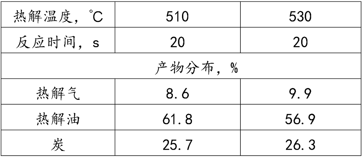
[0049] (1) After being dried and crushed, the pine wood sawdust is continuously sent to the bottom of the pyrolysis reactor from non-condensable gasification to lift into the pyrolysis reactor for pyrolysis, and the reaction time is 0.5-20s. The outlet temperature of the pyrolysis reactor is 500-650°C , the reaction pressure is 0.1-0.4Mpa, generating pyrolysis gas and pine charcoal;

[0050] (2) The pyrolysis gas generated in step (1) is separated from the pine charcoal, the pine charcoal falls into the regenerator, the pyrolysis gas enters the oil-gas separation tank after being condensed by the condenser, and is separated into pyrolysis oil and non-condensable gas;

[0051] (3) The non-condensable gas generated in step (2) enters the bottom of the pyrolysis reactor together with nitrog...


PUM


Abstract

The invention discloses a method for achieving efficient biomass conversion by adopting a catalytic cracking device in a petroleum processing process. Heat generated by burning coke generated in a catalytic cracking process is used for achieving heat self sufficiency of the whole process, meanwhile, through catalytic cracking, modification of biomass pyrolytic tar is achieved, a process of converting biomass into high-quality fuel oil directly is achieved, and the catalytic cracking device is used fully, so that there is no need to build a biomass pyrolysis device individually, the productioncost is reduced, and meanwhile, the problems that during individual biomass oil catalytic cracking modification, coking is prone to happen, and a catalyst is prone to bond and aggregate can be solved.A technology involves a pyrolysis reactor, a riser reactor, a reproducer, a settler, an oil-gas separation tank and a fractionating tower, wherein the pyrolysis reactor is placed in the reproducer, and is used for biomass pyrolysis and liquefaction; a catalytic cracking reactor is used for catalytic cracking of a petroleum fraction and the biomass pyrolytic oil, and a catalytic cracking product is separated into cracking gas, gasoline and diesel fractions through the fractionating tower.

Description

technical field [0001] The invention relates to the field of energy and chemical industry, and more specifically relates to a method for realizing high-efficiency conversion of biomass by using a petroleum fraction catalytic cracking device. Background technique [0002] Energy is the material basis for human survival, and fossil energy occupies a dominant position in energy consumption. However, due to its non-renewable nature, fossil energy is increasingly depleted, and at the same time, problems such as greenhouse gas emissions and environmental pollution caused by the consumption of fossil energy are becoming more and more serious. Driven by the superimposed effect of energy and environment, the development and utilization of renewable energy has attracted more and more attention. Among the many renewable energy sources, biomass energy is favored and abundant, and can be converted into conventional solid, liquid and gaseous fuels. Among them, biomass liquid fuel, that ...

Claims


Application Information

Patent Timeline
IPC IPC(8): C10B53/02C10B57/10C10G1/08C10K1/04
CPCC10B53/02C10B57/10C10G1/086C10K1/04Y02E50/10Y02E50/30Y02P20/584
Inventor 刘熠斌陈小博冯翔杨朝合山红红
Owner CHINA UNIV OF PETROLEUM (EAST CHINA)
Learn More