A differential ion mobility spectrum of a micro-ionization spray ion source and an application method thereof

A differential ion migration and ion source technology, applied in particle separation tubes, ion sources/guns, parts of particle separator tubes, etc., can solve the problems of inability to obtain, good signal strength, etc., and achieve easy technology promotion, good Repeatability and stability, the effect of avoiding bias

Pending Publication Date: 2018-12-21
SHANDONG ANALYSIS & TEST CENT
View PDF14 Cites 5 Cited by
  • Summary
  • Abstract
  • Description
  • Claims
  • Application Information

AI Technical Summary

Problems solved by technology

The present invention aims at the disadvantages that the existing DMS instrument cannot obtain better signal strength and ion transmission efficiency, etc., and proposes a micro-electrospray ion source (Micro-electrospray Ionization, Micro-ESI) which is closed after modification and connected with a typical DMS device installation

Method used


Image

  • A differential ion mobility spectrum of a micro-ionization spray ion source and an application method thereof
  • A differential ion mobility spectrum of a micro-ionization spray ion source and an application method thereof
  • A differential ion mobility spectrum of a micro-ionization spray ion source and an application method thereof

Examples


Embodiment 1

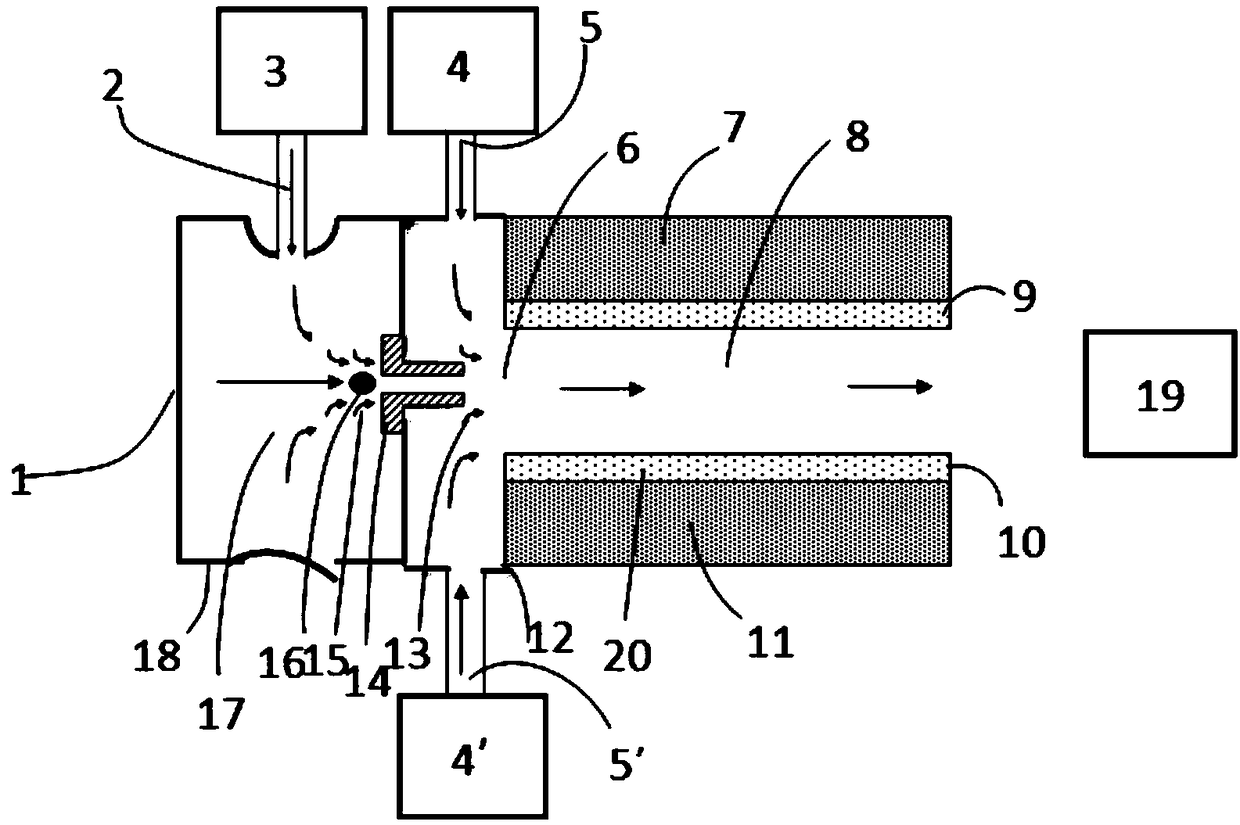
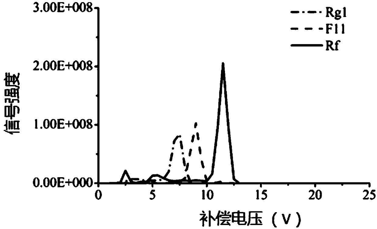
[0041] use figure 1 The mESI-DMS device shown has a plate height of 1.4 mm, a plate length of 8 cm, a width of 2 cm, a mass spectrometer inlet inner diameter of 2 mm, a fused silica capillary inner diameter of 20 microns and an outer diameter of 250 microns, electrospray The high voltage of the ion source is 1.5 kV, and ginsenoside Rg1, Rf and pseudo-ginsenoside F11 are used as analysis samples. These three samples are isomers, and the solution flow rate is 30 microliters per hour. Sodium acetate is added to the samples to assist A sodium peak is formed. The flow rates of the auxiliary gathering gas and auxiliary atomizing gas are set to 600 ml per minute, 99.999% nitrogen is used as the carrier gas, and the temperature is room temperature. 0.1% (molar ratio) of n-propanol is added to the carrier gas as an organic solvent modifier to improve the separation performance of DMS. The DMS is applied with a high-field asymmetric waveform high-frequency voltage with a peak-to-peak vo...

Embodiment 2

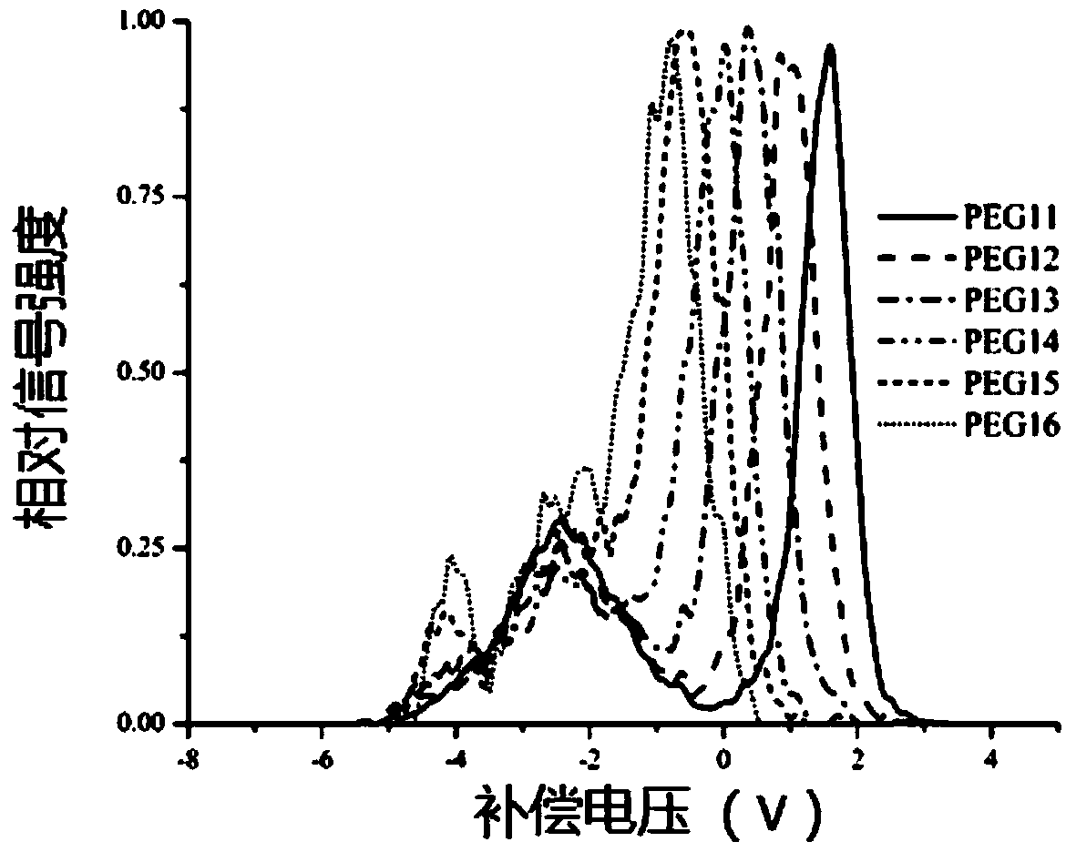
[0044] use figure 1 The mESI-DMS device shown has a plate height of 1.4 mm, a plate length of 8 cm, a width of 2 cm, a mass spectrometer inlet inner diameter of 1 mm, a fused silica capillary with an inner diameter of 50 microns and an outer diameter of 250 microns, electrospray The high voltage of the ion source is 3 kV, polyethylene glycol polymer is used as the analysis sample, and the solution flow rate is 30 microliters per hour. The flow rates of the auxiliary gathering gas and auxiliary atomizing gas are set to 600 ml per minute, 99.999% nitrogen is used as the carrier gas, and the temperature is room temperature. No organic solvent modifier is added to the carrier gas; the DMS is applied with a high-field asymmetric waveform high-frequency voltage with a peak-to-peak voltage of 6 kV; the mass spectrometer inlet is grounded to effectively attract the sample ions migrated from the DMS into the ions In the channel.

[0045] The experimental result is image 3 As shown, the...


PUM

PropertyMeasurementUnit
lengthaaaaaaaaaa
thicknessaaaaaaaaaa

Abstract

The invention belongs to the field of differential ion mobility spectrum, in particular to a differential ion mobility spectrum of a micro-ionization spray ion source and an application method thereof, wherein the mobility spectrum is sequentially arranged as an ion source atomization chamber, an auxiliary gas accumulation chamber and a differential ion mobility spectrum device. The invention adopts the auxiliary atomizing gas to improve the ionization efficiency of the ion source, the auxiliary atomizing gas and the auxiliary gathering gas are combined to reduce the ion diffusion between theion source and the DMS, and the streamlined gas flow also greatly improves the ion transmission rate in the differential ion mobility spectrum migration channel. The design of double gas paths reducesthe disturbance of gas flow when the two gas streams converge, avoids the uneven gas flow rate caused by the instability of mass spectrometer pump in the traditional technology, and ultimately achieves relatively high ion transport efficiency.

Description

Technical field [0001] The invention belongs to the field of differential ion mobility spectroscopy, and specifically relates to a differential ion mobility spectroscopy device of a micro-ionization spray ion source and an application method thereof. The separation of complex compounds is realized by adding an auxiliary atomization device and a concentrated air flow. Background technique [0002] Mass spectrometry technology and corresponding instrument research and development have achieved remarkable development in the past few decades. The large-scale use of high resolution mass spectrometry instruments in the field of analytical chemistry and the emergence of new mass spectrometry ionization technologies have enabled the analysis of most biological, chemical, and environmental samples. The work can be effectively completed on the mass spectrometer. However, more and more challenging and complex samples often require more complicated sample pre-treatment processes and sample p...

Claims


Application Information

Patent Timeline
Patent Type & Authority Applications(China)
IPC IPC(8): H01J49/04H01J49/10G01N27/62
CPCH01J49/0422H01J49/10G01N27/624
Inventor 吴日陈相峰陈德华
Owner SHANDONG ANALYSIS & TEST CENT
Why Eureka
Try Eureka