
Radiofrequency ultrasonic knife with replaceable blade tube

An ultrasonic scalpel and radio frequency technology, applied in the field of radio frequency ultrasonic scalpel, can solve the problems of increasing the amount of medical waste, waste of resources, and high learning costs, and achieve the effects of avoiding secondary cross-infection, improving utilization efficiency, and easy operation

Pending Publication Date: 2018-12-25
武汉半边天医疗技术发展有限公司
View PDF1 Cites 18 Cited by
  • Summary
  • Abstract
  • Description
  • Claims
  • Application Information

AI Technical Summary

Problems solved by technology

[0006] Although the disclosed technical solution can realize the disassembly and replacement of the inner and outer tubes of the ultrasonic knife, the knife tube assembly is used as a disposable consumable as a replacement consumable, and the knife rod and handle are reused, which can maximize the use of the ultrasonic knife and reduce the operation cost. However, the structure of this scheme is complex, there are many parts, the disassembly and installation process is complicated, the operation process requires training and guidance, and the learning cost is high, which is not conducive to popularization
[0007] This solution has several disadvantages that seriously affect the use: 1. Use the outer tube fixing screw to tighten. The doctor wears silicone gloves during the actual cleaning after the operation. Once the outer tube is contaminated with liquid, the outer tube fixing screw will slip, which is inconvenient to operate. It cannot be ensured that the fixing screws can be unscrewed for reliable disassembly of the inner and outer tubes
It is also impossible to ensure that the fixing screws are tightened after replacement, and whether the inner and outer tubes are reliably fixed
2. Due to the large size of the fixing screw, it occupies a certain space, and the torque wrench cannot be used conveniently, so it is difficult to ensure a reliable connection between the tool holder and the transducer
3. The extra fixing screws on the ultrasonic knife are easy to accidentally hang other medical pipelines, which will affect the smooth progress of the operation
[0011] This scheme also has several disadvantages that seriously affect the popularization: 1. Compared with the commonly used ultrasonic scalpel, the ultrasonic scalpel with high-frequency hemostasis function also has the problem that it cannot be disassembled. Contaminants such as tissue and blood remaining in the room, once the cleaning is not thorough, the sterilization is unreliable, which will cause cross-infection of the next patient
2. According to regulations, the ultrasonic scalpel is discarded after one-time use, and the entire cost is spread on one operation, which will increase the medical burden of patients, which is contrary to the national policy of reducing medical expenses
3. The PTFE pad of the forceps on the ultrasonic scalpel is a consumable product, while the life of the blade and handle on the ultrasonic scalpel is not completed in one operation. One-time use will cause waste of resources, increase the amount of medical waste, and cause environmental pollution
The material is suitable for electrostatic discharge, but the conductivity for high-frequency surgery cannot meet the practical requirements
5. The ultrasonic electrical signal and the high frequency electrical signal are input on the same line, and the high frequency (radio frequency) 550kHz high voltage passes through the conductive ring, which interferes with the switching value of low voltage and small current, affecting their normal work
6. The signal input of the two working sources is bundled together, which is not convenient for the doctor to choose to work in a single ultrasound mode, a single high-frequency mode, or two modes to work together according to the surgical needs
7. The solution does not have a separate high-frequency working mode
[0012] Both options have disadvantages

Method used


Image

  • Radiofrequency ultrasonic knife with replaceable blade tube
  • Radiofrequency ultrasonic knife with replaceable blade tube
  • Radiofrequency ultrasonic knife with replaceable blade tube

Examples


Embodiment 1

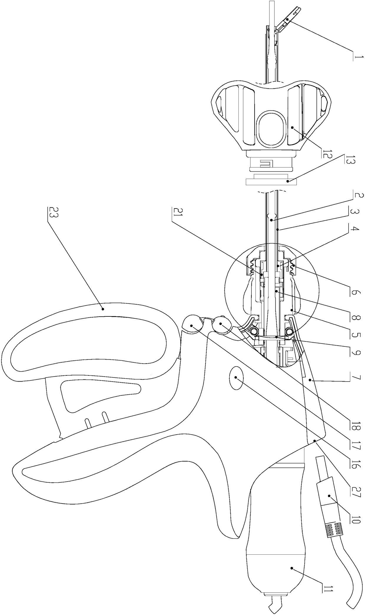
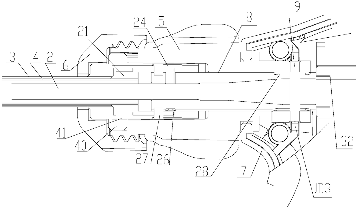
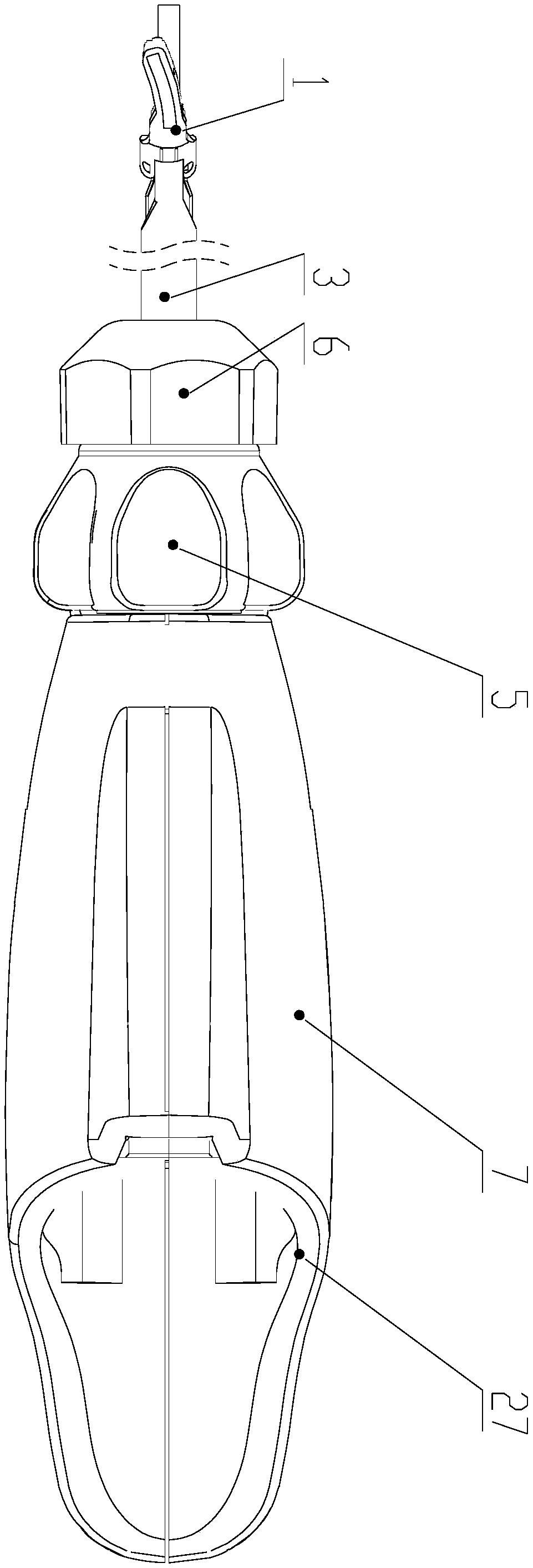
[0089] according to figure 1 , figure 2 , image 3 , Figure 4 , Figure 5 , Figure 6 , Figure 7 , Figure 11 It can be seen that a radio frequency ultrasonic knife that can quickly replace the knife tube includes a knife tube assembly 22, a hook pipe 8, an ultrasonic knife handle 7, a radio frequency plug (with wires) 10, a transducer (with wires) 11, a torque wrench 12, Torque wrench conversion device 13. Wherein the knife tube assembly 22, the drag hook pipe fitting 8, and the pin 9 are all made of medical stainless steel through mechanical processing. The cutter bar 2 is made of titanium alloy material through machining. The pliers head 1 is embedded with a polytetrafluoro pad and made of polytetrafluoro material through machining or molding. Ultrasonic knife handle 7, radio frequency plug 10, torque wrench 12, torque wrench conversion device 13, radio frequency button switch 16 (both sides), ultrasonic button 17, radio frequency plus ultrasonic button 18, hand...


PUM


Abstract

The invention discloses a radiofrequency ultrasonic knife with a replaceable blade tube. A blade tube assembly composed of a clamp head, an outer tube, an inner tube and a knurled knob nut is modularized. Through connection between the inner tube of the blade tube assembly and a hook pipe piece and fastening of a knurled rotary knob and the knurled knob nut, the fastening connection between an ultrasonic knife handle and the blade tube assembly is achieved, so that the inner tube is directly driven to linearly move through opening and closing of an ultrasonic knife handle wrench, and thus opening and closing of the clamp head and a knife rod are controlled. The modularized blade tube assembly can achieve rapid disassembly, separation, replacement of components in the blade tube assembly, the ultrasonic knife is cleaned and disinfected alone, the replacement of the blade tube and clamp head which are likely to be damaged and consumed and the reutilization of a cutter part are achieved,and the cost of medical treatment is reduced.

Description

technical field [0001] The present invention relates to the technical field of medical devices, and more specifically relates to a radio frequency ultrasonic knife with replaceable knife tube, which is used to easily replace the inner and outer tubes during surgery so that the radio frequency ultrasonic knife blade and handle can be used repeatedly, and can be used by different buttons. A device for arbitrarily switching radio frequency working mode, ultrasonic working mode and radio frequency plus ultrasonic working mode. A medical device that can replace bipolar coagulation forceps and ultrasonic scalpel with one device. Background technique [0002] The application of ultrasonic scalpel in surgery is usually to convert and transmit ultrasonic energy into biological tissue, and the thermal effect of mechanical vibration will break the hydrogen bond of tissue protein, denature and solidify protein, especially use the mechanical energy and thermal energy generated by it to c...

Claims


Application Information

Patent Timeline
Patent Type & Authority Applications(China)
IPC IPC(8): A61B18/12A61B17/32
CPCA61B17/320068A61B18/12
Inventor 邱学文孙魁朱卫国
Owner 武汉半边天医疗技术发展有限公司
Learn More