Layering water injection flow intelligent adjusting system under pit

A technology of intelligent adjustment and layered water injection, which is applied in the direction of production fluid, wellbore/well components, wellbore/well valve device, etc., which can solve the problems of heavy monitoring and adjustment workload of layered water injection, and real-time adjustment of water injection volume, etc. , to achieve the effect of reducing the risk of getting stuck and getting stuck, reducing the workload and labor intensity

Active Publication Date: 2018-12-25
华运隆腾机械制造有限公司
View PDF8 Cites 13 Cited by
  • Summary
  • Abstract
  • Description
  • Claims
  • Application Information

AI Technical Summary

Problems solved by technology

[0005] The purpose of the present invention is to provide an intelligent adjustment system for downhole layered water injection flow rate, which is used to solve the existing layered water injection need

Method used


Image

  • Layering water injection flow intelligent adjusting system under pit
  • Layering water injection flow intelligent adjusting system under pit
  • Layering water injection flow intelligent adjusting system under pit

Examples


Embodiment Construction

[0025] Below in conjunction with accompanying drawing, the present invention will be further described:

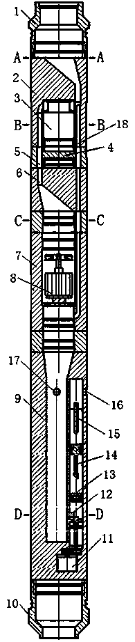
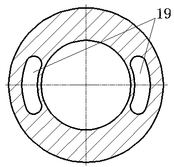
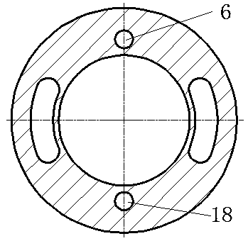
[0026] combine figure 1 , figure 2 , image 3 , Figure 4 , Figure 5 As shown, this downhole layered water injection flow intelligent adjustment system includes an upper joint 1, a tapered flow channel conversion pipe 2, a power generation unit 7, an intelligent water distributor 9, a lower joint 10 and a PCL control unit connected sequentially from top to bottom. There are two partial holes 19 arranged on both sides of the tapered hole flow channel conversion pipe 2, and the upper circular tapered hole is located between the two partial holes 19. Road 6 communicates with water injection branch 18, and a solenoid valve 3 is installed in the middle of the cone-hole flow channel conversion pipe 2. Connect the lower circular cone hole, the lower circular cone hole is narrow at the top and wide at the bottom. The lower circular cone hole communicates with the power gene...


PUM


Abstract

The invention relates to a layering water injection flow intelligent adjusting system under a pit. The layering water injection flow intelligent adjusting system under the pit comprises a PLC controlunit, an upper joint, a cone-hole flow passage converting pipe, a power generation unit, an intelligent water dispenser and a lower joint, wherein the upper joint, the cone-hole flow passage converting pipe, the power generation unit, the intelligent water dispenser and the lower joint are successively connected from top to bottom, two deflected holes are formed in both sides of the cone-hole flowpassage converter pipe, and an upper round taper hole is located between the two deflected holes; the tail end of the upper round taper hole is communicated with a power generation branch and a waterinjection branch, an electromagnetic valve is installed on the cone-hole flow passage converter pipe, and the tail end of the power generation branch is connected with a lower round taper hole; the lower round taper hole is communicated with the power generation unit, and an impeller power generator under the pit is arranged in the power generation unit; the lower end of the power generation unitand the water injection branch are connected with the intelligent water dispenser, a water dispensing cavity of the intelligent water dispenser is communicated with a water outlet cavity through an adjustable water nozzle, a platinum thermistor thermometer, a lever flowmeter and a silicon piezoresistive pressure meter are arranged in the water outlet cavity, and the adjustable water nozzle is connected with a gear motor. Repeated throwing and catching operations are not needed, and the water injection amount can be adjusted in real time.

Description

technical field [0001] The invention relates to a layered water injection system, in particular to an intelligent adjustment system for downhole layered water injection flow. Background technique [0002] Layered water injection is an important technical means to achieve long-term high and stable production in oilfield development. The "bridge type eccentric + steel pipe cable direct reading measurement and adjustment" layered water injection technology has been successfully applied to the measurement and adjustment of layered water injection wells in domestic oilfields. However, this method There are the following problems in use: [0003] (1) To determine the amount of water injection between layers, measuring and adjusting instruments need to be placed layer by layer. This process uses equipment including cable winches, wellhead sealing blowout preventers and wellhead pulley blocks, which requires a lot of manpower and material resources and is time-consuming; [0004] (...

Claims


Application Information

Patent Timeline
IPC IPC(8): E21B43/20E21B34/06E21B41/00
CPCE21B34/06E21B41/0085E21B43/20
Inventor 王金东张隆宇赵海洋韩辉欧凌飞宋美萍
Owner 华运隆腾机械制造有限公司
Why Eureka
Try Eureka