Upper cooling header with variable flow across width

A cooling header and width technology, applied in metal rolling, metal processing equipment, manufacturing tools, etc., can solve the problems affecting the quality of strip steel products, the cooling effect is not obvious, the variable flow range is small, etc., and the comprehensive cooling rate can be achieved. Balanced and consistent, avoiding edge waves and buckling defects, and low manufacturing costs

Active Publication Date: 2019-09-27
YANSHAN UNIV +1
View PDF2 Cites 4 Cited by
  • Summary
  • Abstract
  • Description
  • Claims
  • Application Information

AI Technical Summary

Problems solved by technology

However, the cooling header only relies on the arrangement of two nozzles with different apertures, so the variable flow range achieved is small, and it cannot be accurately controlled according to the fact that the temperature drop rate of the two side sections is greater than that of the middle section, so that the cooling effect is not obvious , will also cause edge waves and scoops in the strip, which will affect the quality of strip products

Method used


Image

  • Upper cooling header with variable flow across width
  • Upper cooling header with variable flow across width
  • Upper cooling header with variable flow across width

Examples


Embodiment 1

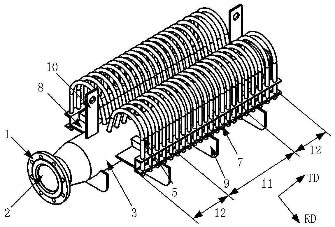
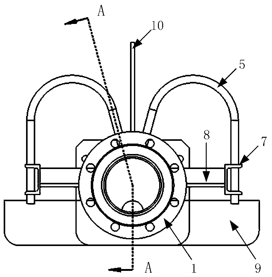
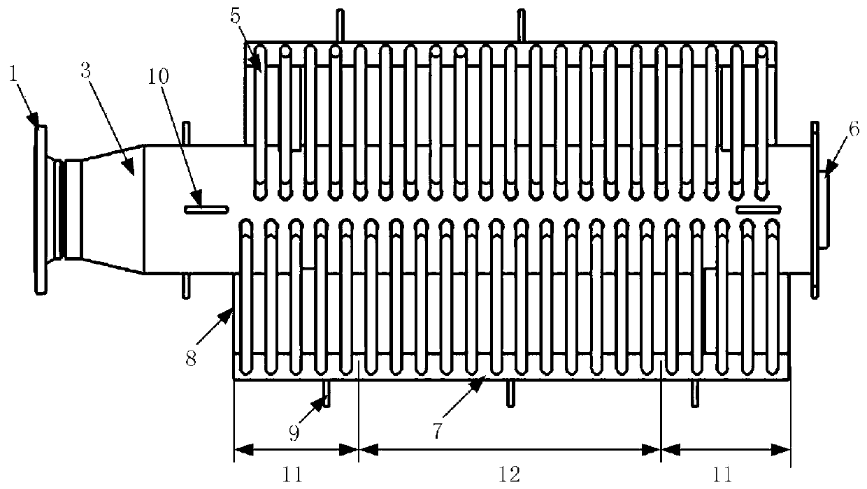
[0061] Embodiment 1 provides the inner diameter D of the throttle ring 4 i In the case of change, the inner diameter of the gooseneck 5 is 18mm, the distribution length is 1008mm, and the number is 22, distributed equidistantly. There are 5 goosenecks 5 on each side 12 of the two sides, and the thickness H of the throttle ring 4 is 4mm. , the maximum inner diameter, that is, the inner diameter D of the throttle ring in the middle section is 12mm, and the minimum inner diameter d of the throttle rings on both sides is 8mm.

[0062] In this embodiment, the minimum bandwidth of the product series is 660 mm, and the width of the two sides is calculated by the width expression of the two sides 12, and α is 0.1:

[0063]

[0064] The distance L between the choke rings on both sides and the position of the outermost choke ring 4 in the middle section 11 i They are:

[0065] L 1 =48mm,L 2 =96mm,L 3 =144mm,L 4 =192mm,L 5 =240mm

[0066] The goosenecks 5 distributed on both s...

Embodiment 2

[0073] Embodiment 2 provides the case when the thickness of throttle ring 4 changes, in order to avoid confusion with embodiment 1, use H in embodiment 2 i Indicates the thickness of the choke ring 4, H represents the thickness of the choke ring in the middle section, that is, the maximum thickness of the choke ring 4, and h represents the minimum thickness of the choke rings on both sides.

[0074] The inner diameter of the goosenecks 5 is 18mm, the distribution length is 1008mm, and the number is 22, distributed equidistantly. There are five goosenecks 5 on each side 12, and the inner diameter of the throttle ring 4 is 11mm, and the maximum wall thickness is That is, the thickness H of the choke ring in the middle section i is 6mm, and the minimum thickness h of the choke rings on both sides is 2mm.

[0075] In this embodiment, the minimum bandwidth of the product series is 660 mm, and the width of the two sides is calculated by the width expression of the two sides 12, and...


PUM

PropertyMeasurementUnit
diameteraaaaaaaaaa

Abstract

The invention discloses an upper cooling manifold with the variable flow in the width direction. The upper cooling manifold comprises a flange, a rectifier tube, a main manifold body, a plurality of throttling rings, a plurality of goosenecks, a sewage draining opening, a positioning frame, horizontal supporting rib plates, vertical supporting rib plates and hanging lugs, wherein the multiple throttling rings and the multiple goosenecks are evenly distributed in the transverse width direction of strip steel. The multiple throttling rings and the multiple goosenecks which are distributed alongthe two sides of the axis of the main manifold body are distributed in an evenly crossed mode in the transverse width direction of the strip steel. The transverse width direction of the strip steel isdivided into a middle section and two side edge parts. The throttling rings located at the middle section are the same as the goosenecks located at the middle section in size, the goosenecks locatedat the two side edge parts are the same in size, the inner diameters or the thickness of the throttling rings are distributed according to a functional form, thus precise adjusting of the cooling water flow and the cooling speed is achieved, finally, the comprehensive cooling speed in the transverse width direction of the strip steel is balanced and consistent, the uniform structure property is ensured, the defects of edge waves and buckling are avoided, the goosenecks are the same in size and belong to the standard specification, the processing and manufacturing costs are low, and the upper cooling manifold is suitable for mass production.

Description

technical field [0001] The invention relates to a cooling technology and shape control technology of hot-rolled strip steel, in particular to an upper cooling header with variable flow in the width direction. Background technique [0002] As an integral part of controlled rolling and controlled cooling technology, laminar cooling directly affects the structure and properties of strip steel, and plays a very important role in the production process of hot rolled strip steel. Now most of the laminar flow cooling goosenecks of hot rolling production lines have the same size, so the water flow and cooling capacity of a single gooseneck are the same, but in the actual cooling process of the steel plate, the cooling water in the middle section of the strip will flow to The flow on both sides produces secondary heat exchange, so usually the two sides dissipate heat faster than the middle section, resulting in a faster temperature drop of the strip steel on both sides than the middl...

Claims


Application Information

Patent Timeline
Patent Type & Authority Patents(China)
IPC IPC(8): B21B45/02
Inventor 黄华贵季策张尚斌高林杨瑞宇张俊鹏燕猛向楠
Owner YANSHAN UNIV
Why Eureka
Try Eureka