A method for removing carbon dioxide from industrial gases by pressure swing adsorption

An industrial gas, pressure swing adsorption technology, applied in chemical instruments and methods, separation methods, gas treatment, etc., can solve the problems of high investment costs and operating costs, achieve strong versatility, reduce investment and operating costs, and reduce investment costs and the effect of running costs

Active Publication Date: 2021-06-04
BEIJING PEKING UNIV PIONEER TECH
View PDF5 Cites 0 Cited by
  • Summary
  • Abstract
  • Description
  • Claims
  • Application Information

AI Technical Summary

Problems solved by technology

[0005] However, the hydrogen recovery rate in the existing technology still needs to be further improved, and its investment cost and operating cost are high. It is necessary to further improve the existing technology so that the investment cost and operating cost can be reduced while increasing the maximum hydrogen recovery rate.

Method used


Image

  • A method for removing carbon dioxide from industrial gases by pressure swing adsorption
  • A method for removing carbon dioxide from industrial gases by pressure swing adsorption
  • A method for removing carbon dioxide from industrial gases by pressure swing adsorption

Examples


Embodiment 1

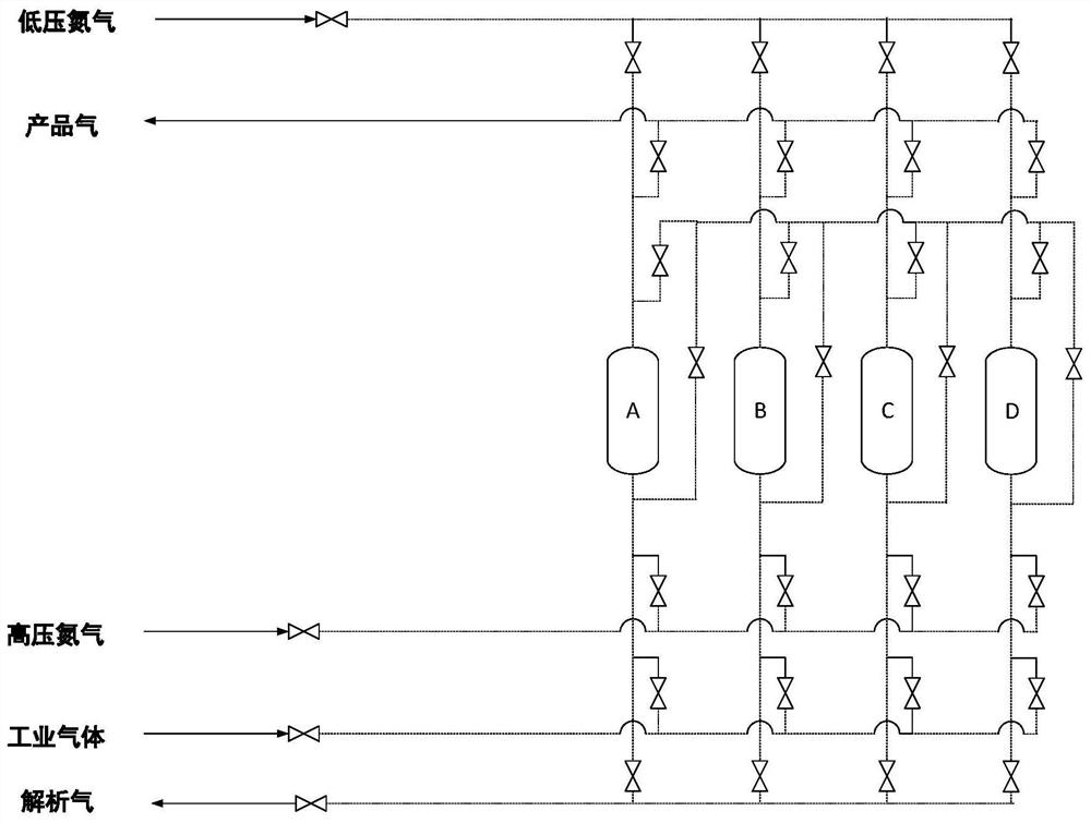
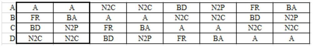
[0028] The pressure swing adsorption device used in Example 1 is a system consisting of four adsorption towers, and the time sequence of one cycle of the system is shown in Table 1.

[0029] Table 1 Cycle time sequence of four-tower pressure swing adsorption process for removing carbon dioxide

[0030]

[0031] As shown in Table 1, in each period of the adsorption regeneration cycle process, each tower of the system is in a different working state. For example, in a period of time shown in the thick line box in Table 1, the working status of each tower is:

[0032] Tower A is in the adsorption step. The industrial gas with a pressure of 1.2MPa (gauge pressure) enters the tower from the bottom of the tower for adsorption. The impurities in the industrial gas are trapped in the adsorption bed by the adsorbent, and the qualified product gas is drawn out from the top of the tower. Tower C is in the reverse discharge step for the first half of the time, and then enters the low-p...

Embodiment 2

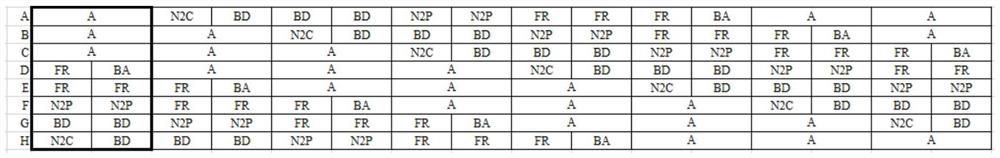
[0034] The pressure swing adsorption device used in Example 2 is a system consisting of eight adsorption towers, and the time sequence of one cycle of the system is shown in Table 2.

[0035] Table 2 The cycle sequence of the eight-column pressure swing adsorption process for carbon dioxide removal

[0036]

[0037] In each period of the adsorption regeneration cycle process, the towers of the system are in different working states. For example, in a period shown in the thick line box in Table 2, the working conditions of each tower are:

[0038] Tower A, Tower B, and Tower C are in the adsorption step. The industrial gas with a pressure of 1.2MPa (gauge pressure) enters the tower from the bottom of the tower for adsorption. The impurities in the industrial gas are trapped in the adsorption bed by the adsorbent. The qualified product The gas is drawn from the top of the tower. The first half of the H tower is in the high-pressure nitrogen replacement step. The high-pressur...


PUM


Abstract

The invention discloses a method for removing carbon dioxide in industrial gas by pressure swing adsorption. The removal of carbon dioxide in industrial gas is realized through a pressure swing adsorption device; the pressure swing adsorption device includes at least four adsorption towers and a plurality of gas flow control Control valves; each adsorption tower is equipped with an adsorbent that can selectively absorb carbon dioxide; industrial gas passes through the adsorption tower, and each adsorption tower undergoes adsorption, high-pressure nitrogen replacement, reverse discharge, low-pressure nitrogen flushing, final filling, and pre-adsorption in sequence. Steps; design different process flows by selecting the time of the steps; set the sequence steps of the multi-tower process by controlling the switch of the valve, and realize the continuous decarbonization of industrial gases containing carbon dioxide through the alternate use of multiple towers to obtain purified gas containing hydrogen. The method of the invention can improve the hydrogen recovery rate of products, reduce investment and operating costs, and has simple process and strong versatility.

Description

technical field [0001] The invention belongs to the technical field of gas separation, and in particular relates to a method for removing carbon dioxide in industrial gas by pressure swing adsorption. Background technique [0002] For the industrial production process involving carbon dioxide, there are two main purposes for dealing with carbon dioxide: one is to purify and remove carbon dioxide from the mixed gas, and the other is to purify carbon dioxide from the mixed gas. [0003] In many industrial production processes, the existence of carbon dioxide will have adverse effects on production and must be removed. For example, the shift gas of ammonia synthesis contains 18% to 28% of carbon dioxide, and carbon dioxide must be removed before entering the refining section of ammonia synthesis. The resulting hydrogen and Nitrogen is used to produce synthetic ammonia; when the raw material gas of synthetic ammonia is desulfurized by ethanolamine cycle, carbon dioxide absorbs H...

Claims


Application Information

Patent Timeline
Patent Type & Authority Patents(China)
IPC IPC(8): B01D53/053
CPCB01D53/053B01D2257/504B01D2259/40066B01D2259/4065Y02C20/40
Inventor 张舟李世刚
Owner BEIJING PEKING UNIV PIONEER TECH
Why Eureka
Try Eureka