
A power transmission line melting device

A transmission line and ice melting technology, applied in cable installation, overhead installation, electrical components, etc., can solve problems such as unsafe hidden dangers, inability to fully cover lines, and scratched lines.

Active Publication Date: 2020-10-27
KAIFENG POWER SUPPLY COMPANY STATE GRID HENAN ELECTRIC POWER
View PDF2 Cites 0 Cited by
  • Summary
  • Abstract
  • Description
  • Claims
  • Application Information

AI Technical Summary

Problems solved by technology

The device uses heating resistors as knives to melt the ice after heating, which cannot fully cover the circuit, and the ice is not completely melted, and the knives are easy to damage or scratch the circuit, causing unsafe hazards

Method used


Image

  • A power transmission line melting device
  • A power transmission line melting device
  • A power transmission line melting device

Examples


Embodiment 1

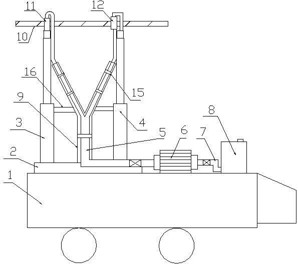
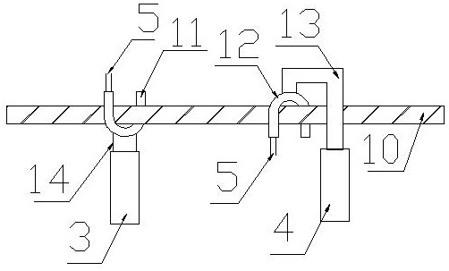
[0035] refer to figure 1 and 2 , this embodiment provides a transmission line ice melting device, including a mobile tool cart 1, a support mechanism arranged on the mobile tool cart 1, and an ice melting mechanism arranged on the support mechanism;

[0036] The mobile tool cart 1 is provided with a centrifugal pump 6 and a liquid storage cylinder 8 storing a liquid deicing agent. The liquid storage cylinder 8 is connected to the inlet of the centrifugal pump 6 through an inlet pipe 7. The centrifugal pump The outlet of 6 is connected with the lower end of the Y-shaped outlet pipeline 5; the support mechanism includes a base 2 fixedly arranged on the mobile tool cart 1, a support frame arranged on the base 2; the support frame includes the first A support rod 3, a second support rod 4 and a Y-shaped fixed groove 9 for supporting the outlet pipe 5; the ice-melting mechanism includes a U-shaped first nozzle arranged at the end of the first support rod 2 11 and the inverted U-s...

Embodiment 2

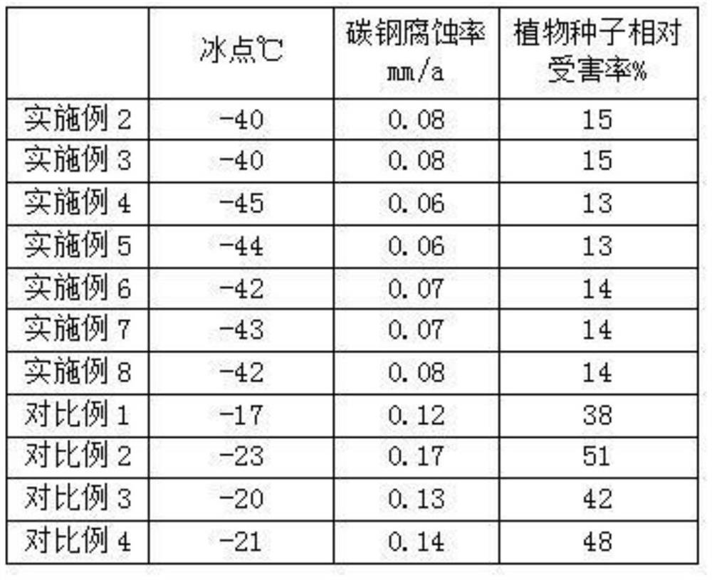
[0045] This embodiment provides a power transmission line melting device. The difference from Embodiment 1 is that the deicing agent in Embodiment 1 is provided, which is made from the ingredients and parts by weight shown in Table 1. The modified Calcium organic acid is made from the ingredients and amounts shown in Table 2.

[0046] Wherein, the coupling agent is silane coupling agent KH550. The surfactant is polyoxyethylene lauryl ether.

[0047] The preparation method of described modified organic acid calcium is:

[0048] S1: Add calcium oxide to the bamboo vinegar, stir at room temperature at a speed of 300r / min for 15min to obtain calcium organic acid;

[0049] S2: Add montmorillonite and coupling agent sequentially to the phosphoric acid solution with a mass fraction of 6%, heat in a water bath at 55-60°C, set the rotation speed at 200r / min and stir for 10min, then add sodium polyphosphate, keep the temperature and rotation speed constant Change, continue to stir 45...

Embodiment 3

[0053] This embodiment provides a power transmission line melting device. The difference from Embodiment 1 is that the deicing agent in Embodiment 1 is provided, which is made from the ingredients and parts by weight shown in Table 1. The modified The consumption of each composition in the calcium organic acid is the same as embodiment 2.

[0054] Wherein, the coupling agent is silane coupling agent KH560. The surfactant is alkylphenol polyoxyethylene ether. The preparation method of the modified calcium organic acid is the same as in Example 2. The preparation method of described deicing agent is with embodiment 2.


PUM


Abstract

The invention discloses a transmission line ice melting device, belonging to the technical field of transmission line maintenance, which comprises a moving tool car, a supporting mechanism and an icemelting mechanism. The mobile tool vehicle is provided with a centrifugal pump and a liquid storage cylinder storing liquid ice-melting agent, wherein the liquid storage cylinder is connected with theinlet of the centrifugal pump through an inlet pipe, and the outlet of the centrifugal pump is connected with the lower end of the Y-shaped outlet pipe; The support mechanism comprises a base and a support frame arranged on the base; The support frame comprises a first support bar, a second support bar and a Y-shaped fixing groove; The ice melting mechanism comprises a U-shaped first nozzle and an inverted U-shaped second nozzle, wherein a first branch of the outlet pipe is connected with the first nozzle, and a second branch of the outlet pipe is connected with the second nozzle. The invention can completely cover the circuit, thoroughly melt ice, and additionally provides a melting agent suitable for the melting device, which has low freezing point, fast melting rate in a short time, remarkable melting effect, and little harm to carbon steel and plants.

Description

technical field [0001] The invention relates to the technical field of power transmission line maintenance, in particular to a power transmission line melting device. Background technique [0002] After entering winter, rain, snow and freezing weather appear in most parts of my country, and transmission lines often suffer from ice-covered disasters of varying degrees. The icing of transmission lines will lead to accidents such as wire galloping, disconnection, tower collapse, insulator flashover, etc., which will bring great inconvenience to the normal operation of the power grid and people's lives. The icing of transmission lines is a complex process, and the amount of icing is related to many factors such as the radius of the wire, the diameter of the supercooled water droplet, the air content, and the temperature. In order to reduce the occurrence of various accidents caused by icing, there are many deicing methods at home and abroad, but the deicing mechanism can be sum...

Claims


Application Information

Patent Timeline
Patent Type & Authority Patents(China)
IPC IPC(8): H02G7/16
CPCH02G7/16
Inventor 南钰宗一刘平杨浩宇朱海槟胡江雪陈鹏高天里
Owner KAIFENG POWER SUPPLY COMPANY STATE GRID HENAN ELECTRIC POWER
Learn More