
System and method for reducing the amount of sulfur oxides in exhaust gas

A waste gas and waste gas pipe technology, which is applied in the direction of chemical instruments and methods, separation methods, combustion methods, etc., can solve the problems of size, weight, robustness, stability, etc., and can not be automatically interchanged, so as to reduce the speed of waste gas and simplify the installation space Effect

Inactive Publication Date: 2019-01-04
YARA MARINE TECH AS
View PDF4 Cites 2 Cited by
  • Summary
  • Abstract
  • Description
  • Claims
  • Application Information

AI Technical Summary

Problems solved by technology

[0011] It is emphasized that while scrubber technologies are known to be suitable for land-based installations, these technologies are not always suitable for marine applications because size, weight, robustness, stability, flow and exhaust gas composition are based on sea and land Parameters that are not automatically interchangeable between scrubber systems
[0012] The purpose of the present application is to provide a scrubbing system that does not create high back pressure on the engine, while allowing multiple engine exhaust pipes to be connected to the scrubber in a simple manner and requiring a limited amount of space

Method used


Image

  • System and method for reducing the amount of sulfur oxides in exhaust gas
  • System and method for reducing the amount of sulfur oxides in exhaust gas
  • System and method for reducing the amount of sulfur oxides in exhaust gas

Examples


Embodiment Construction

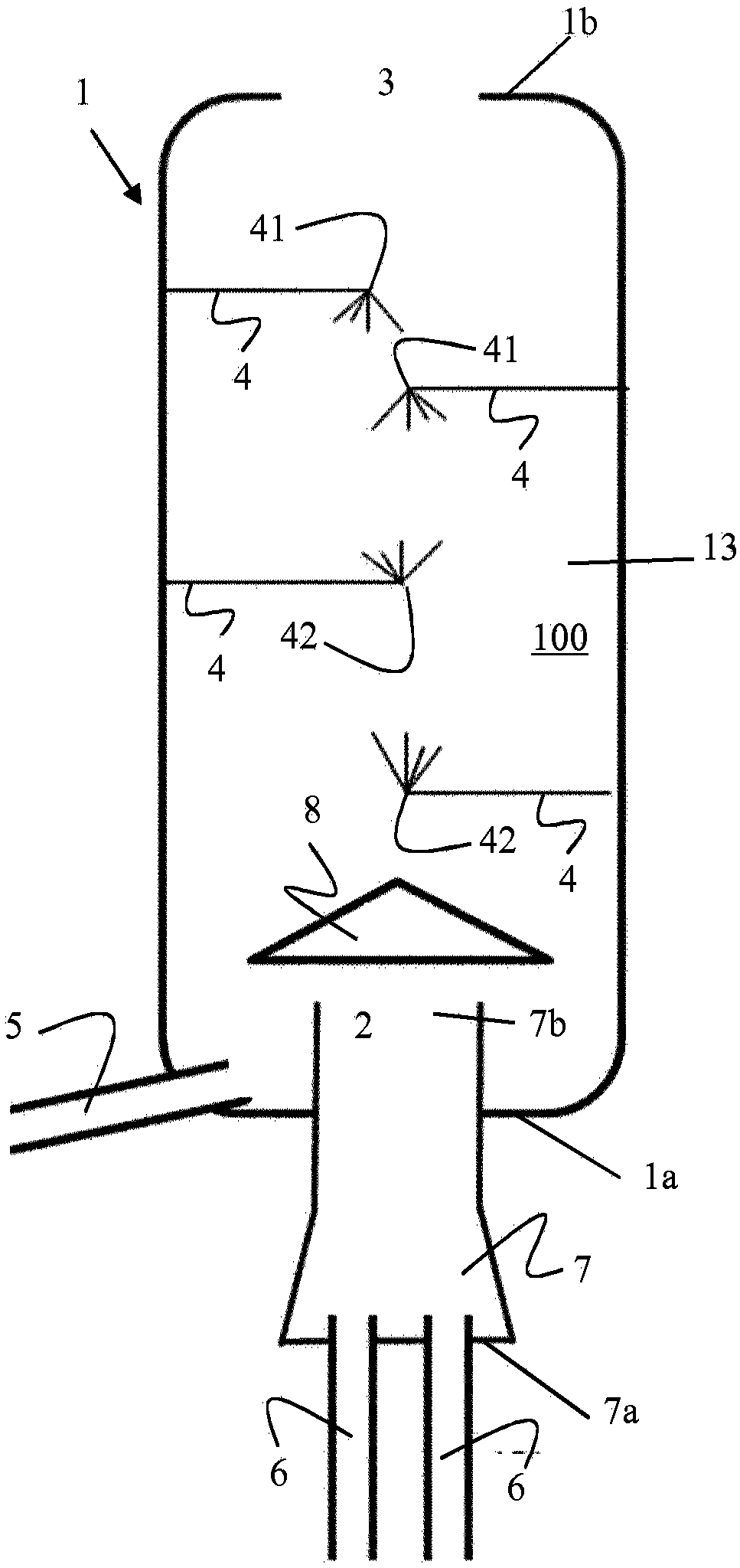
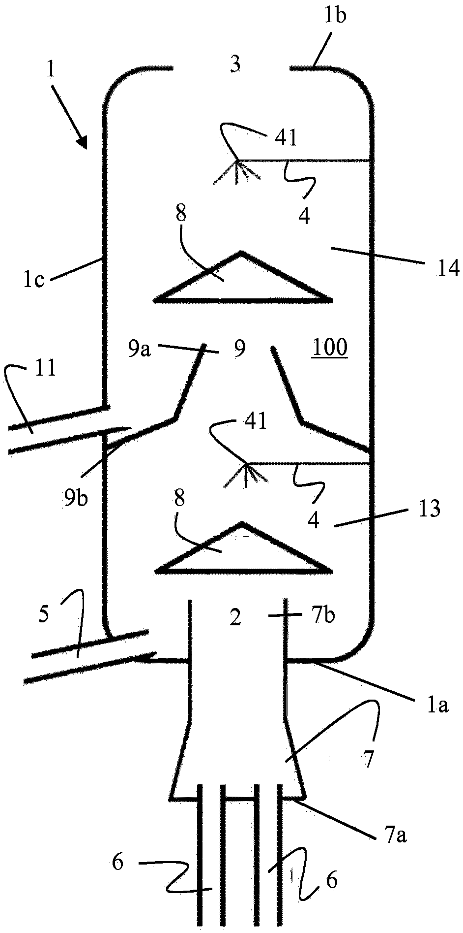
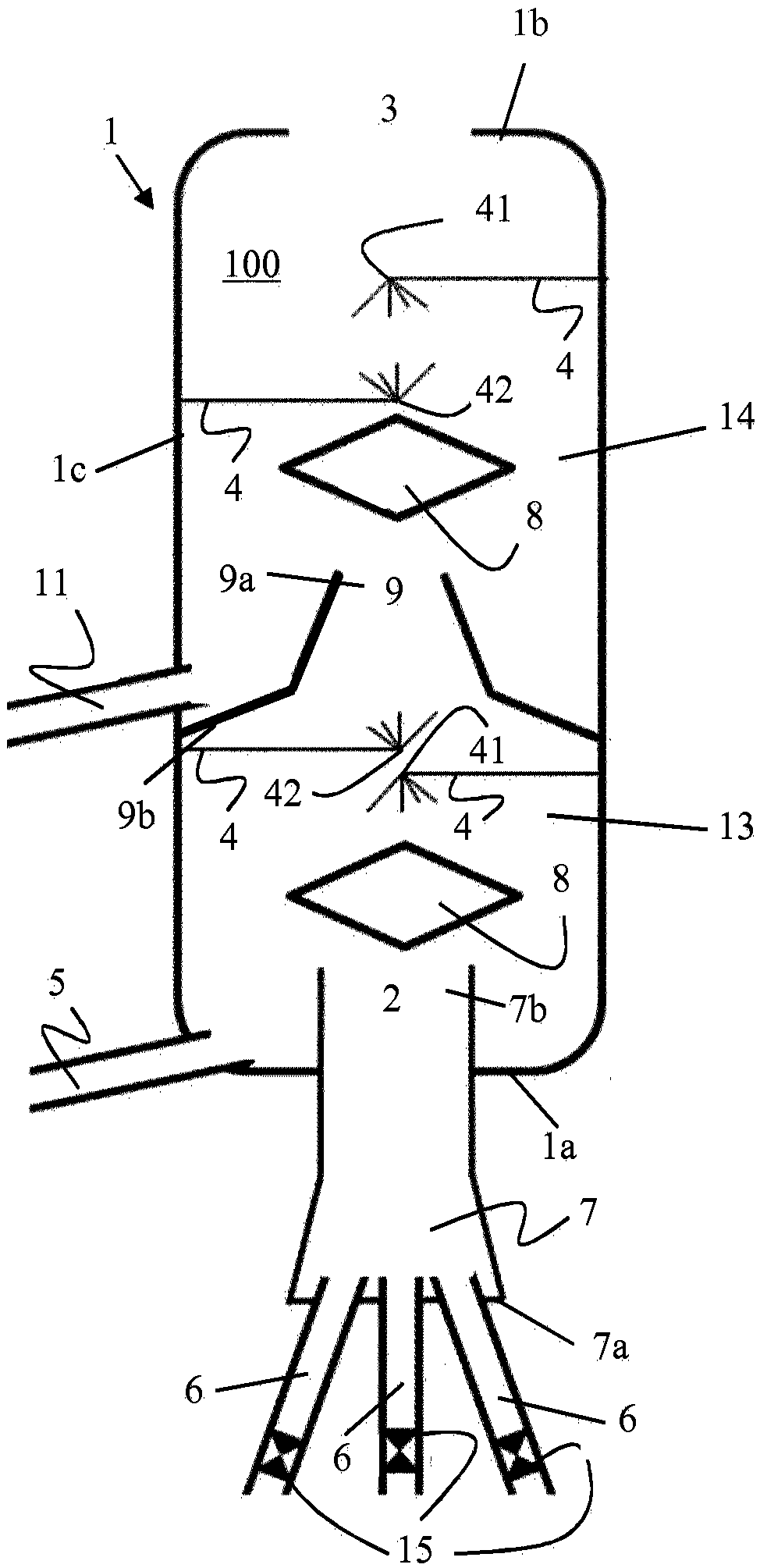
[0069] Such as Figures 1 to 5 As shown, various embodiments of the system according to the present application all include a method for removing SO from the exhaust gas produced by an engine (not shown in the figure), more specifically a marine engine. x The spray tower (1) is arranged to be placed substantially vertically. In its simplest form, the spray tower (1) consists of a cylinder with an inner space (100). In its installed state, the spray tower (1) also has a bottom end (1a) and a top end (1b). More particularly, the bottom end (1a) is located on the opposite side of the top end (1b) of the spray tower (1). More specifically, the cylinders have rotational symmetry about a common longitudinal axis. It is convenient to have the exhaust gas outlet (3) arranged coaxially through the upper end (1b) of the spray tower (1). The central waste gas pipe (7) is located at the bottom (1a) of the spray tower (1). The central exhaust gas tube (7) has an open proximal end (7b)...


PUM

PropertyMeasurementUnit
diameteraaaaaaaaaa

Abstract

The present application relates to a spray tower (1) arranged to be vertically positioned and having an inner space (100), wherein the spray tower comprises, a central exhaust gas pipe (7) arranged for introducing exhaust gas into the inner space of the spray tower through an exhaust gas inlet (2) positioned at a proximal end (7a) of the central exhaust gas pipe, the central exhaust gas pipe beingpositioned at a bottom end (1a) of the spray tower in installed position, the central exhaust gas pipe being in fluid connection with the inner space of the spray tower through an exhaust gas inlet (2) at a top end of the central exhaust gas pipe, and at least one exhaust gas outlet (3 arranged for withdrawing purified exhaust gas from the inner space of the spray tower, the exhaust gas outlet being positioned at a top end (1b) of the spray tower in installed position, the exhaust gas outlet being in fluid connection with the inner space of the spray tower, wherein from the exhaust gas inletto the exhaust gas outlet, a general exhaust gas flow is passing through the inner space of the spray tower, one or more spray devices (41, 42) configured to provide a stream of scrubber liquid withinthe inner space of the spray tower counter current to the general exhaust gas flow, and at least two engine exhaust gas pipes (6) being in fluid connection with the distal end (7b) of the central exhaust gas pipe. Furthermore, a method for reducing the amount of SOx in exhaust gas is described.

Description

technical field [0001] The present application relates to the technical field of exhaust gas purification. More specifically, this application relates to the reduction of sulfur oxides (SO x ) content to purify the exhaust gas of the ship. Background technique [0002] Fossil fuels are burned for many different purposes in industrial processes. Unfortunately, the combustion of fossil fuels produces several pollutants that have been found to be harmful to the environment. In particular, sulfur oxides and nitrogen oxides are major components of "acid rain". Sulfur is a naturally occurring element in crude oil that is concentrated in residual components of the crude oil distillation process. The amount of sulfur in fuel oil depends mainly on the origin of the crude oil and to a lesser extent on the refining process. Typically, this value is around 1.5-4% w / w for fuels on a global scale. These values ​​lead to high concentrations of SO in the flue gas 2 . For example, wh...

Claims


Application Information

Patent Timeline
Patent Type & Authority Applications(China)
IPC IPC(8): B01D53/14B01D53/18B01D53/50B01D53/78F01N3/04F01N13/00
CPCB01D53/1481B01D53/18B01D53/504B01D53/78F01N13/004F23J15/04B01D2251/402B01D2251/602B01D2251/604B01D2252/1035B01D2257/302B01D2259/4566F23J2215/20F23J2219/40F01N2590/02F01N3/04Y02T10/12B01D53/14B01D53/1493B01D53/185B01D47/063
Inventor 希亚姆·巴哈杜尔·塔帕彼得·斯特兰德贝里
Owner YARA MARINE TECH AS
Learn More