Laser-water jet combined drilling device

A combined drilling and water jet technology, applied in drilling with liquid/gas jets, drilling equipment, drilling with thermal energy, etc., can solve the problems of low drilling efficiency, high drilling cost, etc. Wear reduction effect

Active Publication Date: 2019-01-08
SOUTHWEST PETROLEUM UNIV
View PDF3 Cites 14 Cited by
  • Summary
  • Abstract
  • Description
  • Claims
  • Application Information

AI Technical Summary

Problems solved by technology

[0005] The purpose of the present invention is to overcome the deficiencies of the prior art, to propose a laser-water jet combined drilling device for oil and gas resources and geothermal en...

Method used


Image

  • Laser-water jet combined drilling device
  • Laser-water jet combined drilling device

Examples


Embodiment Construction

[0022] The present invention will be further described below in conjunction with the accompanying drawings and this embodiment.

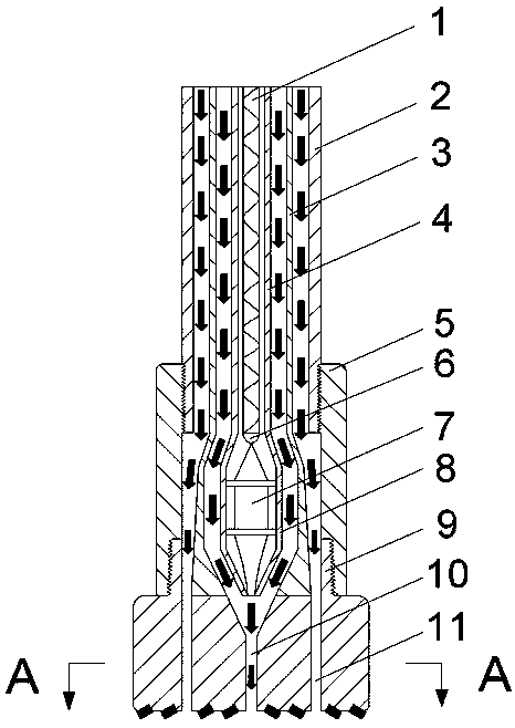
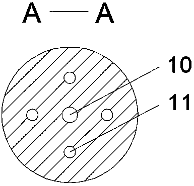
[0023] Such as figure 1 As shown, a laser-water jet combined drilling device of the present invention is mainly composed of a drill pipe 2, a drill collar 5, a drill bit 9, an optical fiber 1, a clean water pipeline 3, an optical fiber protection tube 4, a beam shaping device 7, and a beam shaping device shell 8. The water guide laser beam channel 10, the laser head 6, and the drill bit flow channel 11 are composed; the drill pipe 2 is provided with an optical fiber protection tube 4 and a clean water pipeline 3, and the optical fiber protection tube 4 is provided with an optical fiber 1, and the clean water is protected by the optical fiber. The annular passage between the pipe 4 and the clean water pipe 3 flows, and the drilling fluid flows in the annular passage between the clean water pipe 3 and the drill pipe 2. By setting the optical fiber pro...


PUM


Abstract

The invention relates to a laser-water jet combined drilling device which mainly comprises a drill rod, a drill collar, a drill bit, an optical fiber, a clean water pipe, a fiber protection tube, a beam shaping device, a beam shaping device shell, a water guiding laser beam channel, a laser head, and a drill bit flow channel. The fiber protection tube and the clean water pipe are arranged in the drill rod and the fiber, cleaning water, and drilling liquid are separated. The beam shaping device and the beam shaping device shell are arranged in the drill collar. The laser head emits laser and the laser passes through the beam shaping device; cleaning water is collected in a V-shaped-cross-section channel at the center of the drill bit; a water-guiding laser beam is formed and is emitted fromthe water guiding laser beam channel. On the basis of the thermal effect of the laser and the cavitation of the cleaning water, the rock is broken and the rock fragments are prevented from entering the beam shaping device by jet of the cleaning water. The drilling fluid is jetted from the drill bit flow channel on the broken rock by boosting of a pump on the well. The rock is broken by several kinds of modes; the difficulty of rock breaking by the drill bit is reduced; the drill tool wearing is reduced; and the rock breaking efficiency is improved.

Description

technical field [0001] The invention relates to a laser-water jet combined drilling device, which is used in the fields of oil and gas resources, geothermal energy drilling and exploitation, and the like. Background technique [0002] As domestic and foreign oil and gas exploration work gradually shifts to deep wells and ultra-deep wells, harder rocks and lower drilling speeds greatly reduce drilling efficiency and increase drilling costs. [0003] Currently, roller cone bits, PDC bits and composite bits are most used in oil drilling. When drilling in homogeneous soft formations, conventional PDC bits have the characteristics of fast drilling speed, long service life, and many footages. The adaptability of the drill bit is poor, the ROP is high but unstable, and the cutting teeth are prone to impact damage and high temperature wear, resulting in bit damage and short service life; and the rock breaking method of the roller cone bit causes its rock breaking efficiency to be lo...

Claims


Application Information

Patent Timeline
IPC IPC(8): E21B7/14E21B7/18E21B17/18E21B10/00
CPCE21B7/14E21B7/18E21B10/00E21B17/18
Inventor 黄志强朱晶张文琳邓嵘马亚超周操杨雪莹谢豆
Owner SOUTHWEST PETROLEUM UNIV
Why Eureka
Try Eureka