
Dynamic performance testing device for belt transmission system

A technology of system dynamics and testing equipment, which is applied in the field of mechanical transmission, can solve the problems of V-belt and tensioner wear, large vibration and noise of the transmission system, and short service life, and achieves a simple structure, high versatility, and easy realization. Effect

Active Publication Date: 2019-01-11
SICHUAN UNIV
View PDF9 Cites 8 Cited by
  • Summary
  • Abstract
  • Description
  • Claims
  • Application Information

AI Technical Summary

Problems solved by technology

At present, the design and layout of the engine accessory gear train is mainly carried out through theoretical analysis, but the theoretical analysis has greatly simplified the V-belt and each accessory wheel, which cannot accurately reflect the dynamic performance of the V-belt transmission system, causing many problems. When the V-belt transmission system designed at that time actually works, the tension of the V-belt fluctuates too much, the V-belt and the tensioner wear prematurely, the service life is short, and the vibration and noise of the entire transmission system are too large.
Therefore, the design scheme of the engine accessory gear train proposed only by theoretical analysis can no longer meet the requirements for higher performance of the engine accessory gear train at the present stage, and it is necessary to verify and improve the theoretical model with experiments
However, in actual work, due to factors such as the compact structure of the engine accessory gear train, many dynamic characteristics such as belt tension fluctuations cannot be measured, which seriously affects the performance evaluation of the designed engine accessory gear train.

Method used


Image

  • Dynamic performance testing device for belt transmission system
  • Dynamic performance testing device for belt transmission system
  • Dynamic performance testing device for belt transmission system

Examples


Embodiment Construction

[0024] Below by embodiment and in conjunction with accompanying drawing, the present invention will be further described:

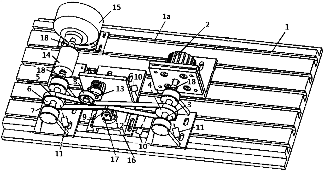
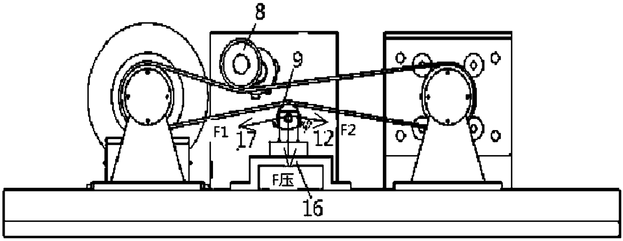
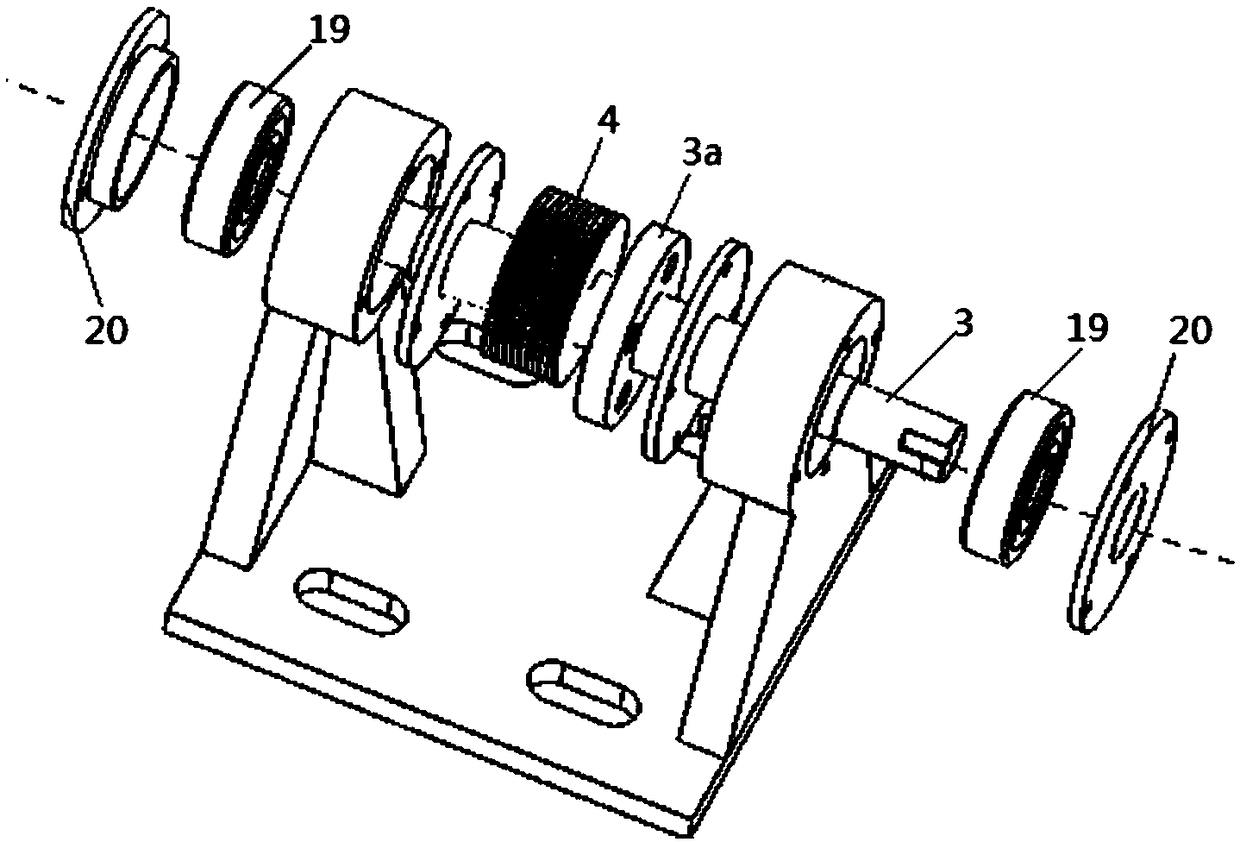
[0025] combine figure 1 — figure 2 As shown, a test device for dynamic performance of a belt transmission system is mainly composed of a test platform 1, a servo motor 2, an input shaft 3, a driving wheel 4, a belt 5, a driven wheel 6, an output shaft 7, a tensioner 8, and an idler wheel 9 , Laser displacement sensor 10, laser rotational speed sensor 11, pressure sensor 12, potentiometer 13, torque sensor 14, magnetic powder brake 15, pressure sensor mount 16, idler mount 17, coupling 18, etc.

[0026] The servo motor 2, the input shaft 3, the driving wheel 4, the belt 5, the driven wheel 6 and the output shaft 7 are connected in sequence and installed on the test platform 1. A tensioner 8 is arranged above the belt 5, and an idler 9 is arranged below the belt 5, thereby forming a belt transmission system. The tensioning pulley of driving pulley 4, dr...


PUM


Abstract

The invention relates to a dynamic performance testing device for a belt transmission system. The dynamic performance testing device comprises a testing platform, a servo motor, an input shaft, a driving wheel, a belt, a driven wheel, an output shaft, a tensioner and an inert wheel. Laser displacement sensors are used for measuring transverse vibration of a belt section when the belt operates; laser rotating speed sensors are combined with reflective pulses generated by reflective paper pasted to the driving wheel and the driven wheel to measure the rotating speed; a pressure sensor is used for measuring belt compressing force borne by the inert wheel, and conducting back calculation to obtain belt tensioning force; a potentiometer is used for measuring swing vibration of the tensioner; and a magnetic powder brake is used for providing load torque for the belt transmission system, and a torque sensor is used for measuring a load torque value of the belt transmission system. The dynamicperformance testing device is simple in structure, easy to realize and low in cost, can be transformed into various dynamic characteristic testing platforms for the belt transmission system by replacing the type of belt wheels, and provides guidance for the design of an engine accessory transmission system by serving as an experimental verification platform for a dynamic model of the belt transmission system.

Description

technical field [0001] The invention relates to a dynamic performance testing platform of a belt transmission system, which belongs to the field of mechanical transmission. Background technique [0002] The belt drive system, especially the V-belt drive system is widely used in the engine accessory wheel train, which is mainly composed of a V-belt, a crankshaft pulley, a tensioner, an alternator pulley, a water pump pulley, an oil pump pulley, Composed of accessory wheels such as air-conditioning compressor pulleys. Compared with ordinary V-belts, multi-V belts have lower bending stiffness and have multiple ribs (large contact area), so the structure of multi-V belt transmission system is more compact, the load capacity is stronger, and there are more driven accessories. Since the tensioner contains a spring damping mechanism, it is mainly used to automatically adjust the tension of the belt, avoid slippage of the V-belt and excessive tension fluctuations, and suppress vibr...

Claims


Application Information

Patent Timeline
IPC IPC(8): G01M13/023
CPCG01M13/023
Inventor 朱浩樊伟
Owner SICHUAN UNIV
Features
  • Generate Ideas
  • Intellectual Property
  • Life Sciences
  • Materials
  • Tech Scout
  • Unparalleled Data Quality
  • Higher Quality Content
  • 60% Fewer Hallucinations
Learn More