Femtosecond laser machining and monitoring method and device based on confocal Raman-LIBS-mass spectroscopy detection
A femtosecond laser processing and monitoring device technology, applied in the field of femtosecond laser processing monitoring, can solve the problems of easy axial drift of samples, in-situ detection of complex morphological performance parameters of samples, etc., and achieve high-precision real-time fixed focus problems, The effect of improving the axial position monitoring ability and solving the drift problem
- Summary
- Abstract
- Description
- Claims
- Application Information
AI Technical Summary
Problems solved by technology
Method used
Image
Examples
Embodiment 1
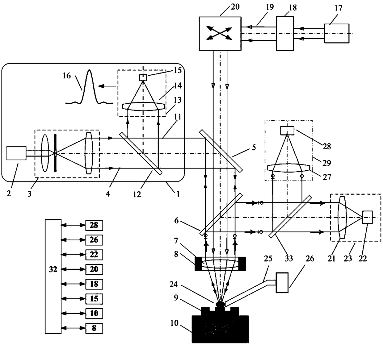
[0049] Such as figure 1 As shown, the computer 32 performs feedback control on the two-dimensional scanner 20, the precision workbench 10, and the axial scanner 8 to realize the three-dimensional scanning and position adjustment of the processing and monitoring of the sample 9; the femtosecond laser processing system consists of a femtosecond laser 17 , a laser space-time shaping module 18, and a two-dimensional scanner 20; the confocal detection module 13 may be composed of a detection objective lens 14 and an intensity detector 15; and the intensity detector 15 is located at the focus position of the detection objective lens 14.
[0050] The implementation steps of the femtosecond laser processing monitoring method detected by confocal Raman-LIBS-mass spectrometry are as follows:
[0051] 1) Place the sample 9 on the precision workbench 10, and the precision workbench 10 drives the sample 9 to perform scanning motion;
[0052] 2) Before processing, use the confocal axial mo...
Embodiment 2
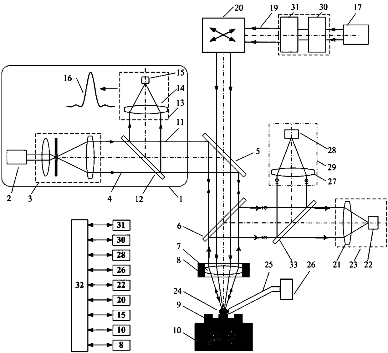
[0061] Such as figure 2 As shown, the laser space-time shaping module 18 is composed of a space shaper 30 and a time shaper 31, and adjusts the time-domain and space-domain parameters of the beam emitted by the femtosecond laser 17, so as to optimize the femtosecond laser processing performance.
[0062] All the other are identical with embodiment 1.
Embodiment 3
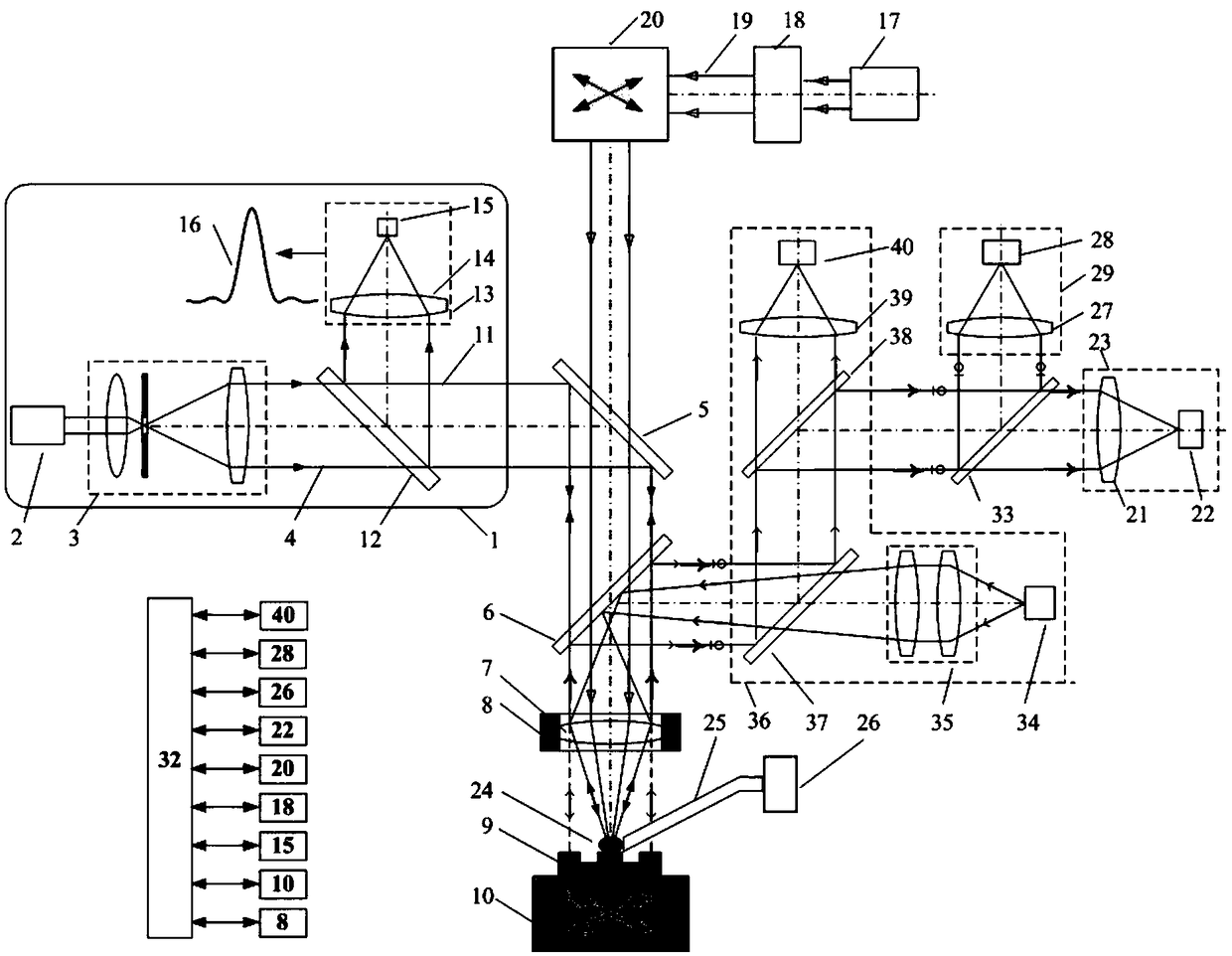
[0064] Such as image 3 As shown, before processing, after the sample 9 is placed on the precision workbench 10, the sample 9 is roughly aligned using the microscopic imaging module 36, and the light emitted by the white light source 34 passes through the illumination system 35, the illumination beam splitter 37, and the After the color mirror B6 and the objective lens 7, a parallel light beam is generated to uniformly irradiate the sample 9, and the illumination light reflected by the sample 9 is reflected by the illumination beam splitter 37 and then imaged on the CCD 40 through the imaging lens 39, so that the position and imaging area of the sample 9 can be obtained, and then The inclination and position of the sample 9 can be judged.
[0065] All the other are identical with embodiment 1.
PUM
 Abstract
Description
Claims
Application Information
 - R&D
- Intellectual Property
- Life Sciences
- Materials
- Tech Scout
- Unparalleled Data Quality
- Higher Quality Content
- 60% Fewer Hallucinations
Browse by: Latest US Patents, China's latest patents, Technical Efficacy Thesaurus, Application Domain, Technology Topic, Popular Technical Reports.
© 2025 PatSnap. All rights reserved.Legal|Privacy policy|Modern Slavery Act Transparency Statement|Sitemap|About US| Contact US: help@patsnap.com


