A traction type mobile substation

A mobile substation, traction type technology, applied in the field of substations, can solve the problems of inability to pass through cables smoothly, easy to hang up cables of substations, etc., and achieve the effects of excellent mechanical properties and insulation properties, light weight and strong adhesion

Active Publication Date: 2019-01-11
国网河南省电力公司西峡县供电公司
View PDF4 Cites 0 Cited by
  • Summary
  • Abstract
  • Description
  • Claims
  • Application Information

AI Technical Summary

Problems solved by technology

However, this invention cannot smoothly pass through areas with low cable heights, and it is easy to hang up the cables above the substation body

Method used


Image

  • A traction type mobile substation
  • A traction type mobile substation
  • A traction type mobile substation

Examples


Embodiment 1

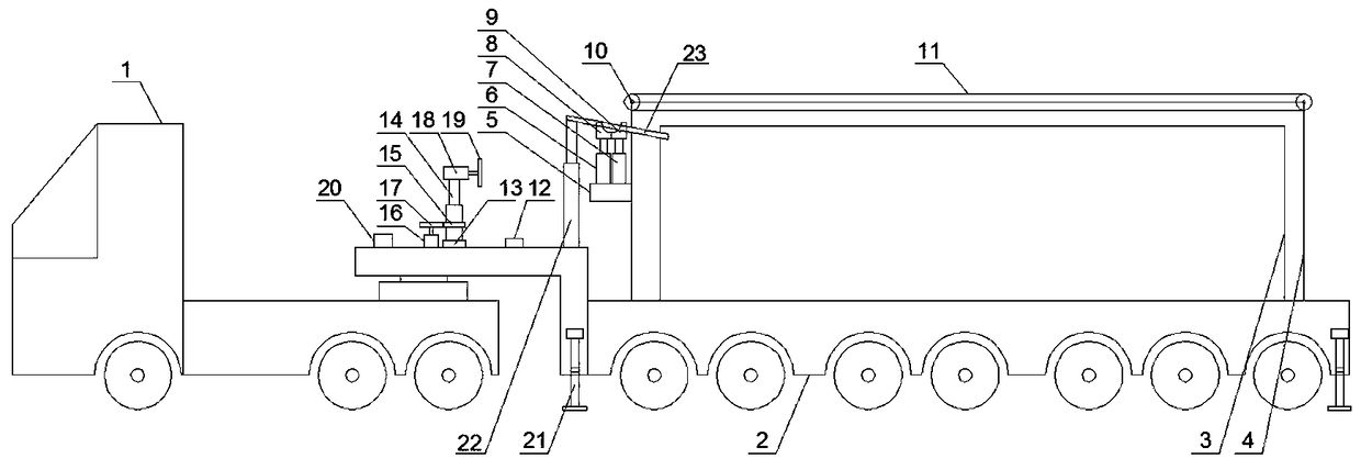
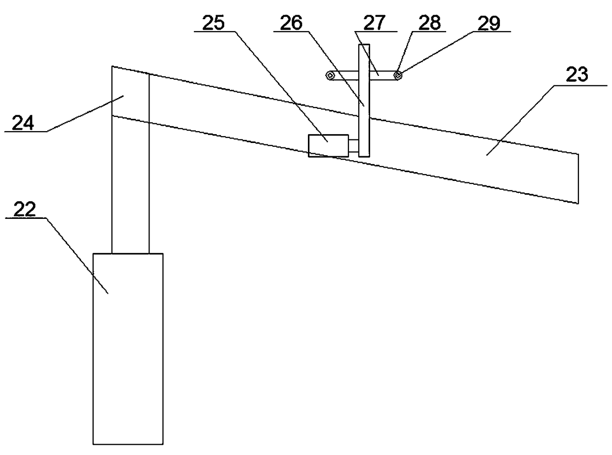
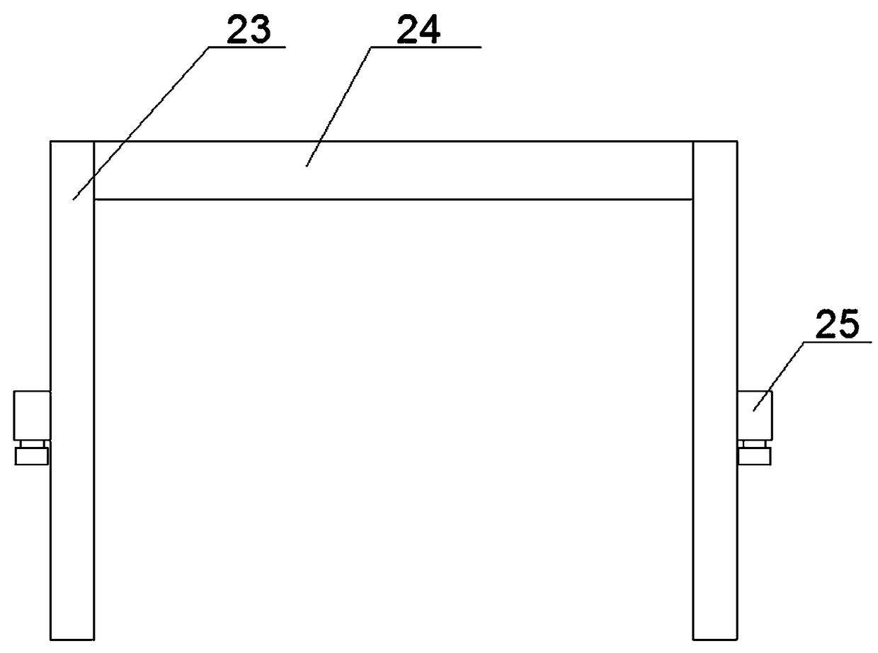
[0038] like Figure 1-4 As shown, a traction type mobile substation includes a tractor 1 and a trailer 2. The trailer 2 is provided with a substation body 3, the substation body 3 is covered with a protective frame 4, and the upper part of the front end of the trailer 2 is provided with a A protection mechanism for hanging up the cables located above the substation body 3 during transportation; an auxiliary mechanism arranged on the trailer and located in front of the protection mechanism;

[0039] The protection mechanism includes a platform 5 arranged on the side of the front end of the protection frame 4 , a left automatic lifting rod 6 and a right automatic lifting rod 7 arranged side by side on the platform 5 , and are arranged on the upper end of the left automatic lifting rod 6 . The left top block 8 is arranged on the right top block 9 at the upper end of the right automatic lifting rod 7, and the quarter-arc groove on the right side of the left top block 8 is opened o...

Embodiment 2

[0050] The difference between it and Example 1 is that the components and their contents contained in the waterproof layer are: 16 parts by weight of polyaniline, 2.5 parts by weight of polymethyl methacrylate, 7 parts by weight of chloroform, N,N-dichloromethane 42 parts by weight of methylformamide, 16 parts by weight of sodium silicate, 2.8 parts by weight of sodium lauryl sulfate, 8 parts by weight of nano-silicon dioxide, 6 parts by weight of sodium methyl silicate, tetrachloroterephthalic acid 3.7 parts by weight of methyl ester, 8.9 parts by weight of cinnamaldehyde, 23 parts by weight of acetone, and 48 parts by weight of deionized water.

Embodiment 3

[0052] The difference between it and Example 1 is that the components and their contents contained in the waterproof layer are: 17 parts by weight of polyaniline, 3 parts by weight of polymethyl methacrylate, 7.5 parts by weight of chloroform, N,N-dichloromethane 44 parts by weight of methylformamide, 16.5 parts by weight of sodium silicate, 3 parts by weight of sodium lauryl sulfate, 9 parts by weight of nano-silicon dioxide, 6.1 parts by weight of calcium stearate, dimethyl tetrachloroterephthalate 3.9 parts by weight of ester, 9 parts by weight of polyaspartic acid, 24 parts by weight of acetone, and 50 parts by weight of deionized water.


PUM

PropertyMeasurementUnit
Thicknessaaaaaaaaaa
Thicknessaaaaaaaaaa
Tensile strengthaaaaaaaaaa

Abstract

The invention discloses a traction type mobile substation, comprises a tractor and a trailer, wherein the trailer is provided with a transformer substation body; the upper cover of the transformer substation body is provided with a protective frame; the upper front end of the trailer is provided with a protective mechanism for avoiding hanging the cable above the transformer substation body duringtransportation; and an auxiliary mechanism arranged on the trailer and located at the front of the protective mechanism. The invention has the advantages of high automation, convenience and flexibility, can avoid hanging up the cable above the transformer substation body during transportation, and can bind the line when passing through, thus providing convenience for subsequent vehicles.

Description

technical field [0001] The invention relates to the technical field of substations, in particular to a traction type mobile substation. Background technique [0002] The wide application of electric energy has promoted changes in various fields of social production, ushered in the era of electric power, and the second technological revolution in modern history. Since the 20th century, the great development of the power system has made the power resources more fully developed, and the industrial layout has become more reasonable. all aspects of daily life. The development level and technical level of the power system have become one of the symbols of the economic development level of various countries. [0003] The power system consists of power plants, transmission lines, substations, and distribution networks. A substation is a power facility in the power system that transforms voltage, receives and distributes electrical energy, controls the flow of power, and adjusts v...

Claims


Application Information

Patent Timeline
IPC IPC(8): H02B7/06B60P3/00C09D179/02C09D7/61C09D7/63C09D7/65B08B1/04
CPCH02B7/06C09D7/63C09D7/65C09D179/02C09D7/61B60P3/00C08L2205/03C08K2201/011B08B1/32C08L33/12C08K13/02C08K3/34C08K5/41C08K3/36C08K5/12
Inventor 吴少昱李晨贺张益铭杜永玺孙枫淦别志攀
Owner 国网河南省电力公司西峡县供电公司
Why Eureka
Try Eureka