Multiwavelength diffusion optical tomography system

A tomography and imaging system technology, which is applied in the directions of using light for diagnosis and tomography for diagnosis and diagnosis, can solve the problems of reducing the detection efficiency of traditional imaging systems, high structural complexity, optical signal loss, etc., and achieve signal detection. The effect of high efficiency, low structural complexity and low R&D cost

Inactive Publication Date: 2019-01-15
XIDIAN UNIV
View PDF5 Cites 6 Cited by
  • Summary
  • Abstract
  • Description
  • Claims
  • Application Information

AI Technical Summary

Problems solved by technology

[0004] In order to improve the imaging effect, the number of excitation and detection fibers required in the imaging system will increase, and the corresponding system will become more and more bulky, making the structure complexity of the traditional

Method used


Image

  • Multiwavelength diffusion optical tomography system
  • Multiwavelength diffusion optical tomography system
  • Multiwavelength diffusion optical tomography system

Examples


Example Embodiment

[0027] Embodiment one

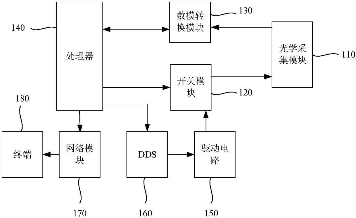
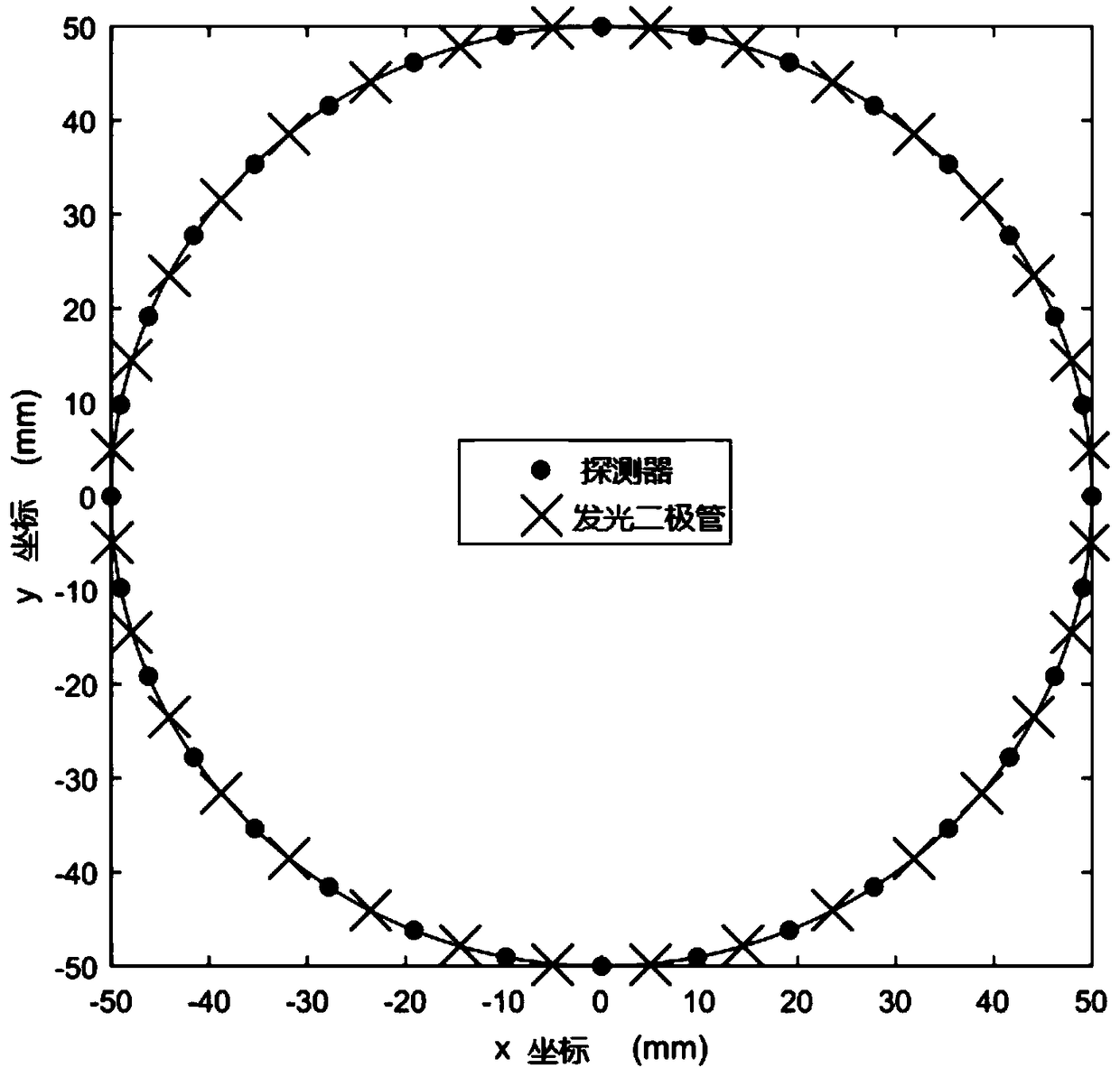
[0028] See figure 1 and figure 2 , figure 1 A schematic diagram of a multi-wavelength diffuse optical tomography system provided by an embodiment of the present invention, figure 2 A schematic diagram of the arrangement of a light emitting diode and a detector provided by an embodiment of the present invention. Specifically, the multi-wavelength diffuse optical tomography system may include:

[0029] An optical collection module 110, configured to generate an excitation light source, and detect tomography and collect data according to the excitation light source;

[0030] A switch module 120, electrically connected to the optical collection module 110, for controlling the excitation light source to be turned on or off;

[0031] A digital-to-analog conversion module 130, electrically connected to the optical acquisition module 110, for receiving the acquisition data of the optical acquisition module 110, and converting the acquisition data into fi...

Example Embodiment

[0043] Embodiment two

[0044] Please continue to see figure 1 and figure 2 . This embodiment introduces the multi-wavelength diffuse optical tomography system proposed by the present invention in detail on the basis of the above embodiments. The system includes:

[0045] Optical acquisition module 110, switch module 120, digital-to-analog conversion module 130, processor 140, drive circuit 150, frequency synthesizer 160, network module 170 and terminal 180;

[0046] Wherein, the optical acquisition module 110 is a plurality of light-emitting diodes and a plurality of detectors, the light-emitting diodes generate excitation light sources, and the detectors detect faults according to the excitation light sources to form and collect data. The light-emitting diodes and detectors are arranged on the flexible printed circuit board at equal intervals, so that they can be attached to the surface of the experimental phantom or biological tissue. The flexible printed circuit boar...


PUM


Abstract

The invention relates to a multi-wavelength diffusion optical tomography system. The system comprises an optical acquisition module (110), which is used for generating an excitation light source and detecting tomography acquisition data according to the excitation light source; a switch module (120) electrically connected to the optical acquisition module (110) for controlling on/off of the excitation light source; a digital-to-analog conversion module (130) electrically connected to the optical acquisition module (110), configured to receive acquisition data of the optical acquisition module(110) and convert the data into digital signal data; a processor (140) electrically connected to the switch module (120) and the digital-to-analog conversion module (130) for controlling on/off of each switch in the switch module (120). The imaging system provided by the invention forms an optical acquisition module through a plurality of light emitting diodes and a plurality of detectors, improves the signal detection efficiency, saves the development cost of the imaging system, reduces the structural complexity, and further reduces the cost of the system.

Description

technical field [0001] The invention belongs to the technical field of optical imaging, and in particular relates to a multi-wavelength diffusion optical tomography system. Background technique [0002] Diffuse Optical Tomography (DOT) is a non-invasive, high-safety, and highly sensitive optical imaging method. Model, distribution map of optical absorption coefficient and scattering coefficient in three-dimensional space of tissue. [0003] At present, DOT imaging mainly has the following three imaging methods: steady state, frequency domain and time domain imaging methods. At present, the industry generally uses a photomultiplier tube (Photomultiplier Tube, PMT for short) as a detector, and a laser diode with modulation (Laser Diode, LD for short) as an excitation light source. After the beam comes out of the LD, it enters a 1×N optical switch to switch the excitation channel, and then transmits the beam to the surface of the experimental phantom or biological tissue thro...

Claims


Application Information

Patent Timeline
IPC IPC(8): A61B5/00G01N21/01
CPCA61B5/0059A61B5/0073G01N21/01
Inventor 朱守平王民马骋周欣欣陈睿博曹旭
Owner XIDIAN UNIV
Why Eureka
Try Eureka