A prosthetic valve prosthesis with an anchor

A technology of artificial valves and fixing parts, which is applied in the field of medical devices, can solve the problems of reducing the service life of the valve, compression of the heart's own tissue, and poor leakage prevention effect, and achieve the effect of reducing the service life of the valve and enhancing the clamping effect

Active Publication Date: 2019-01-15
NINGBO JENSCARE BIOTECHNOLOGY CO LTD
View PDF10 Cites 20 Cited by
  • Summary
  • Abstract
  • Description
  • Claims
  • Application Information

AI Technical Summary

Problems solved by technology

The problem with the said patent is that even if the natural mitral valve annulus can be well anastomosed and coapted, contacting the mitral valve annulus with the radial expansion of the stent mesh will still cause compression on the surrounding tissues of the mitral valve annulus
At the same time, it can be seen from the accompanying drawings of the embodiments of the patent that the diameter of the valve prosthesis is the diameter of the stent, and the cross-sectional area of ​​the stent is at least the area of ​​the mitral valve annulus. left ventricular outflow tract
Finally, the valve leaflets are sutured on a non-circular stent, and the fitting of the valve leaflets in the non-circular area is bound to be affected, reducing the service life of the valve
[0009] In summary, the clamping force of the fixture in the prior art depends on the size of the space between the fixture and the stent, and the clamping of the valve leaflets can only be completed through the cooperation of the stent body. The valve annulus contacts, and the success rate is low; at the same time, the delivery device must also have a larger caliber to fit into the stent body, and the artificial valve hinders the ventricular outflow tract; the existing stent body has caused damage to the heart's own tissue. Excessive compression, poor leak-proof effect

Method used


Image

  • A prosthetic valve prosthesis with an anchor
  • A prosthetic valve prosthesis with an anchor
  • A prosthetic valve prosthesis with an anchor

Examples


specific Embodiment 1

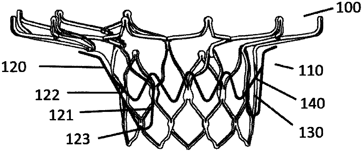
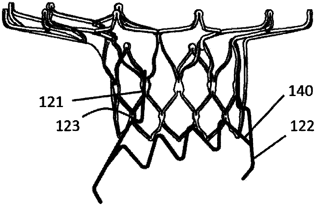
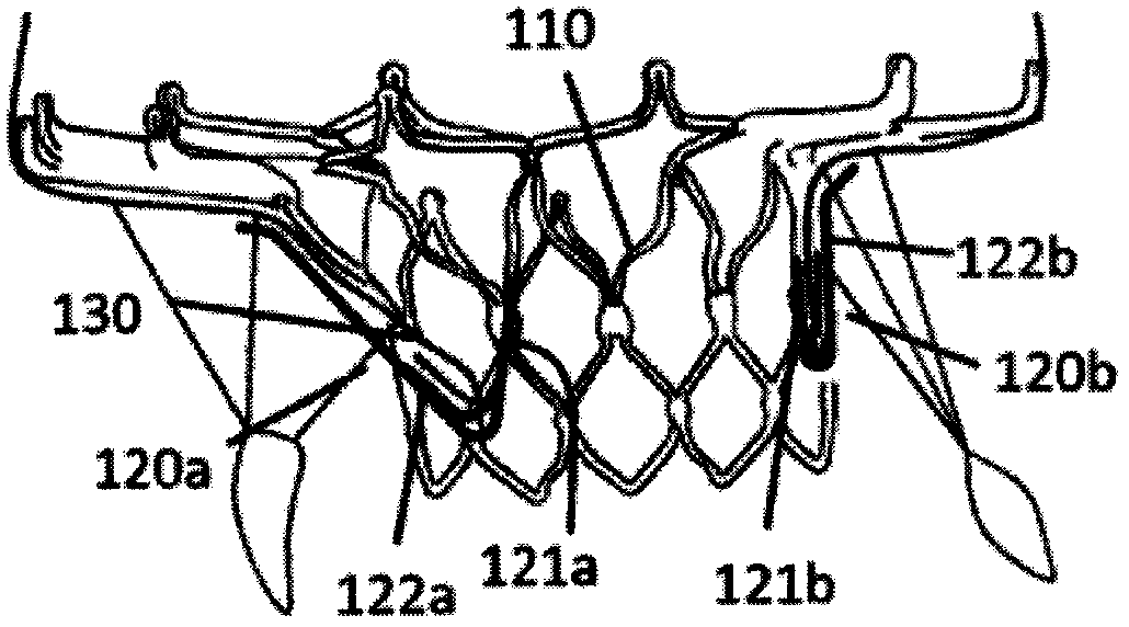
[0041] Such as Figure 1a and Figure 1b As shown, this embodiment introduces an artificial valve prosthesis 100 with a fixing part, which includes a stent body 110 having a channel for blood circulation and at least one fixing part 120, and the fixing part 120 is connected to the The bracket body 110, the fixing member 120 includes a lower extension section 121 and an upper extension section 122, one end of the lower extension section 122 is connected to the bracket body 110 as a fixed end, and the other end of the lower extension section 121 is along the The axis of the stent body 110 extends proximally, and after passing through the bending region 123, it extends distally in the opposite direction and connects with the upper extension section 122, which is located at the bottom of the lower extension section 121. On the outside, a valve leaflet accommodation cavity 130 is formed between the lower extension section 121 and the upper extension section 122, and the fixing memb...

specific Embodiment 2

[0045] As another embodiment, such as Figure 3a and Figure 3b As shown, a prosthetic valve prosthesis 200 with a fixing part includes a stent body 210 having a channel for blood circulation and at least one fixing part 220, the fixing part 220 is connected to the stent body 210, the The fixing part 220 includes a lower extension section 221 and an upper extension section 222, one end of the lower extension section 222 is connected to the bracket body 210 as a fixed end, and the other end of the lower extension section 221 is along the axis of the bracket body 210 The direction of the heart line extends to the proximal end, and after passing through the bending area 223, it extends to the distal end in the opposite direction and is connected to the upper extension section 222, the upper extension section 222 is located outside the lower extension section 221, and the lower extension section 222 is located outside the lower extension section 221. The leaflet accommodation cav...

Embodiment approach

[0046] The stent body 210 further includes a valve sewing section 211 and an atrial positioning section 212 , the distal end of the valve sewing section 211 is connected to the proximal end of the atrial positioning section 212 . Different from the fixing part extending from the valve sewing section in the prior art, as an embodiment of the present invention, the lower extension section 221 is connected to the atrial positioning section 212 of the stent body 210, the The fixing part 220 is independent of the valve sewing section 211, which has the advantage of avoiding the contraction of the valve sewing section driven by the force of the valve from affecting the effect of clamping the leaflets, while allowing the valve sewing section of the present invention to be compared with the existing The size of the valve sewing section in the technology is small, which reduces the impact on the left ventricular outflow tract, which is conducive to sheath retraction and the selection of...


PUM


Abstract

The present application relates to a prosthetic valve prosthesis with an anchor, includes a bracket body having a passage for supplying blood flow and at least one fixing member, the fixing member isconnected with the bracket body, the fixing member includes a lower extension section and an upper extension section, one end of the lower extension section is connected with the bracket body as a fixed end, the other end of the lower extension extends proximally along the axis of the bracket body, extending distally in the opposite direction after passing through the bent region and connected tothe upper extension. The upper extension section is located on the outer side of the lower extension section, and a leaf receiving cavity is formed between the lower extension section and the upper extension section. The fixing member is further provided with a lamination device, and when the fixing member is completely released, the self-body leaf is stacked in the leaf receiving cavity. The clamping force of the fixation part of the prosthetic valve prosthesis is not influenced by the space between the stent body and the fixation part, and the influence on the blood outflow channel after thestent body is released is greatly reduced.

Description

Technical field: [0001] The invention belongs to the field of medical equipment, and in particular relates to an artificial valve prosthesis with a fixing part. technical background: [0002] The human heart has four chambers and four valves, the mitral valve, tricuspid valve, aortic valve and pulmonary valve. Among them, the mitral valve is located between the left atrium and the left ventricle, and is composed of five parts: leaflets, valve ring, papillary muscles, chordae and junction. The mitral valve acts like a one-way valve. When the heart is diastolic, the mitral valve opens to allow blood to flow from the left atrium into the left ventricle. When the heart is in systole, the mitral valve closes to prevent blood from flowing from the left ventricle of the heart to the left ventricle. Left atrial regurgitation. [0003] According to the latest epidemiological survey data of Western developed countries such as the United States, mitral valve insufficiency (also known...

Claims


Application Information

Patent Timeline
Patent Type & Authority Applications(China)
IPC IPC(8): A61F2/24
CPCA61F2/2409A61F2/2412A61F2/2418A61F2/2427A61F2210/0014A61F2220/0008A61F2220/0016A61F2250/006
Inventor 曹鹏陈志李毅斌鲁侃
Owner NINGBO JENSCARE BIOTECHNOLOGY CO LTD
Why Eureka
Try Eureka