EGR rate correction system and method based on filling factor of internal combustion engine

A technology of internal combustion engine and factor, applied in the field of correction based on the system, EGR rate correction system based on internal combustion engine charge factor, EGR rate correction system, can solve the problems of wrong principle, difficulty in popularization, inaccurate calculation, etc., and increase durability Sexual risk, easy to promote, and low-cost effects

Active Publication Date: 2019-01-15
深圳环境能源研究院有限公司
View PDF5 Cites 16 Cited by
  • Summary
  • Abstract
  • Description
  • Claims
  • Application Information

AI Technical Summary

Problems solved by technology

This approach not only requires the addition of additional pressure sensors, but also cannot account for the degradation of the EGR valve and cooler
[0010] The second type of method is to use the temperature signals of the gas temperature sensors of the intake manifold and exhaust manifold to calculate the EGR rate. This method also needs to add additional sensors, and the calculation is very inaccurate. In principle, some methods are even Incorrect
[0012] The above technical solution has problems such as inaccurate or even wrong calculation of EGR rate, need to use additional expensive sensors beyond the range of the permanent sensor of the engine, etc., which increases the cost and increases the durability risk of the sensor, so it is not practical and difficult to promote

Method used


Image

  • EGR rate correction system and method based on filling factor of internal combustion engine
  • EGR rate correction system and method based on filling factor of internal combustion engine
  • EGR rate correction system and method based on filling factor of internal combustion engine

Examples


Embodiment 1

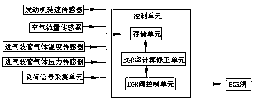
[0055] Such as figure 1 As shown, the present embodiment is an EGR rate correction system based on the charge factor of a turbocharged heavy-duty diesel engine, including a control unit, an engine speed sensor, an air flow sensor, an intake manifold gas pressure sensor, an intake manifold The pipe gas temperature sensor is connected with the load signal acquisition unit.

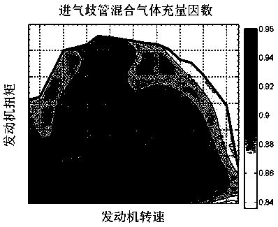
[0056] The control unit includes a storage unit, an EGR rate calculation and correction unit, and an EGR valve control unit, wherein: the storage unit stores the charge factor calibration map, and the rotational speed sensor, air flow sensor, intake manifold gas pressure sensor, intake manifold gas The data collected by the temperature sensor and the load signal collection unit and the calibration value or correction value of the target EGR rate. The load signal acquisition unit of this embodiment collects torque data.

[0057] The EGR valve control unit controls the opening of the EGR valve according to t...


PUM


Abstract

The invention relates to an EGR rate correction system and method based on the filling factor of an internal combustion engine, and belongs to the field of engines. The method is based on the fillingfactor calibration pulse spectrum in the laboratory standard environment. The strong correlation between the filling factor and the inlet manifold gas temperature is adopted to conduct temperature correction to the filling factor. The actual EGR rate is calculated with the definition equation of filling factor. The actual EGR rate is compared with the target EGR rate calibration value or modifiedvalue to complete closed loop feedback control of the EGR valve opening. The EGR rate correction system and method can accurately determine the EGR rate of the engine in practical use when the EGR system and an intercooler deviate from laboratory calibration conditions due to the operation reasons such as fouling or efficiency change; additional sensors in addition to standing sensors are not required to added; and the characteristics of rich functions and being suitable for promotion are achieved.

Description

technical field [0001] The invention relates to an EGR rate correction system, in particular to an EGR rate correction system based on the charge factor of an internal combustion engine, and also relates to a correction method based on the system, which belongs to the field of engines. Background technique [0002] Exhaust Gas Recirculation (EGR for short) technology is one of the most effective measures to control nitrogen oxide emissions. It has been widely used in advanced low-emission internal combustion engines in the United States, Europe, Japan and other countries and in China that meet the latest emission regulations. Or national six diesel engines, but also widely used in gasoline engines and gas fuel internal combustion engines. [0003] EGR technology is one of the most important energy-saving and environmental protection technologies, and its importance can be compared with the post-processing devices widely used in various internal combustion engines. One of th...

Claims


Application Information

Patent Timeline
Patent Type & Authority Applications(China)
IPC IPC(8): F02D41/00
CPCF02D41/005F02D41/0077F02D2200/02F02D2200/04F02D2200/0406F02D2200/06F02D2200/101
Inventor 辛千凡
Owner 深圳环境能源研究院有限公司
Why Eureka
Try Eureka