Low temperature flue gas waste heat utilization, desulphurization, denitration and white smoke elimination integrated system of industrial furnace

A low-temperature flue gas, industrial furnace technology, applied in the direction of reducing greenhouse gas, furnace, waste heat treatment, etc., can solve the problems of high pollutant emission concentration, large pollutant emission, serious environmental pollution, etc., to save investment and reduce occupation. Floor area, the effect of improving thermal efficiency

Pending Publication Date: 2019-01-15
上海孚旺炉业有限公司 +1
View PDF0 Cites 14 Cited by
  • Summary
  • Abstract
  • Description
  • Claims
  • Application Information

AI Technical Summary

Problems solved by technology

[0008] At the same time, since the flue gas produced by fuel combustion contains a large amount of water vapor (content 10-20%), its latent heat of vaporization (accounting for about 10% of the low calorific value of the fuel) is discharged with the flue gas,

Method used


Image

  • Low temperature flue gas waste heat utilization, desulphurization, denitration and white smoke elimination integrated system of industrial furnace
  • Low temperature flue gas waste heat utilization, desulphurization, denitration and white smoke elimination integrated system of industrial furnace
  • Low temperature flue gas waste heat utilization, desulphurization, denitration and white smoke elimination integrated system of industrial furnace

Examples


Embodiment 1

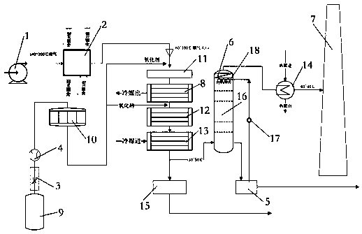
[0042] like figure 1 As shown, it also includes an oxidant system 9, an oxidant activator 10, a denitration catalyst 11, a second flue gas condensation and denitration reactor 12, a third flue gas condensation and denitration reactor 13, and a flue gas warmer 14. The oxidant system 9 is set corresponding to the flow regulating valve 3, and the flow meter 4 is respectively connected to the outlet of the flue gas channel of the multi-strand refrigerant heat exchange system 2 and the flue gas channel outlet of the first flue gas condensation and denitrification reactor 8 through the oxidant activator 10 Correspondingly, the denitration catalyst 11 is arranged at the entrance of the flue gas channel of the first flue gas condensation and denitration reactor 8, the first flue gas condensation and denitration reactor 8, the second flue gas condensation and denitration reaction The device 12 and the third flue gas condensation and denitrification reactor 13 are arranged corresponding...

Embodiment 2

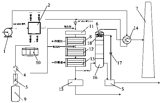
[0044] like figure 2 As shown, it also includes an oxidant system 9, an oxidant activator 10, a denitration catalyst 11, a second flue gas condensation and denitration reactor 12, a third flue gas condensation and denitration reactor 13, and a flue gas warmer 14. The oxidant system 9 is set corresponding to the flow regulating valve 3, and the flow meter 4 is respectively connected to the outlet of the flue gas channel of the multi-strand refrigerant heat exchange system 2 and the flue gas channel outlet of the first flue gas condensation and denitrification reactor 8 through the oxidant activator 10 Correspondingly, the denitration catalyst 11 is arranged at the entrance of the flue gas channel of the first flue gas condensation and denitration reactor 8, the first flue gas condensation and denitration reactor 8, the second flue gas condensation and denitration reaction The device 12 and the third flue gas condensation and denitrification reactor 13 are arranged correspondin...

Embodiment 3

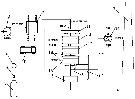
[0046] like image 3 As shown, it also includes an oxidant system 9, an oxidant activator 10, a denitration catalyst 11, a second flue gas condensation and denitration reactor 12, a third flue gas condensation and denitration reactor 13, and a flue gas warmer 14. The oxidant system 9 is set corresponding to the flow regulating valve 3, and the flow meter 4 is respectively connected to the outlet of the flue gas channel of the multi-strand refrigerant heat exchange system 2 and the flue gas channel outlet of the first flue gas condensation and denitrification reactor 8 through the oxidant activator 10 Correspondingly, the denitration catalyst 11 is arranged at the entrance of the flue gas channel of the first flue gas condensation and denitration reactor 8, the first flue gas condensation and denitration reactor 8, the second flue gas condensation and denitration reaction The device 12 and the third flue gas condensation and denitrification reactor 13 are arranged corresponding...


PUM


Abstract

The invention discloses a low temperature flue gas waste heat utilization, desulphurization, denitration and white smoke elimination integrated system of an industrial furnace. The system comprises asupercharging wind turbine, a multi-refrigerant heat exchange system, a flow control valve, a flow meter, a flue gas condensation and denitration reactor, an alkaline pool, a demisting filter and a chimney. The system has the following advantages that convenience is provided for operation of the industrial furnace, and online construction is realized; fuel consumption is reduced, and the thermal efficiency of the industrial furnace is improved; the service life of system equipment and parts is ensured; flue gas waste heat utilization, desulphurization, denitration and white smoke elimination are integrated; the denitration efficiency is >=80% and the desulphurization efficiency is >=90%; water consumption is reduced; the land occupation area is reduced, and the cost is reduced; droplet water in the discharged flue gas is reduced; the concentration of pollutants in the local region near the chimney is reduced; energy is saved, environment pollution is reduced, and visual pollution is eliminated; energy-saving, emission-reducing, water-saving and steam-saving are all realized; the operation cost is low; and the application range is wide.

Description

technical field [0001] The invention relates to an integrated system for utilization of waste heat from low-temperature flue gas of an industrial furnace and desulfurization, nitric acid and white smoke elimination. Background technique [0002] The conventional desulfurization and denitrification currently applied are two independent systems. And the reaction temperature required by each is different. [0003] The temperature range of the denitrification reaction is 250~590°C. The desulfurization reaction temperature is 50~60°C. [0004] In a conventional desulfurization system, the temperature of the flue gas entering the desulfurization tower is generally around 120°C, while the desulfurization reaction requires a temperature of 50-60°C. Therefore, it is necessary to cool the flue gas with a large amount of precious water, so that when the flue gas is finally discharged into the chimney , with a high water content. If the flue gas is not reheated, a "wet chimney" phen...

Claims


Application Information

Patent Timeline
IPC IPC(8): F27D17/00F23J15/00F23J15/06F23J15/02F23J15/04F23J15/08
CPCF23J15/006F23J15/02F23J15/04F23J15/06F23J15/08F23J2215/10F23J2215/20F27D17/004F27D17/008Y02E20/30Y02P10/25
Inventor 付玲君
Owner 上海孚旺炉业有限公司
Why Eureka
Try Eureka