
Continuous light-optical frequency comb locking device and locking method

An optical frequency comb and locking device technology, applied in the laser field, can solve the problems of difficult elimination of laser noise and complex structure, and achieve the effects of phase noise suppression, simple circuit operation and low noise

Active Publication Date: 2019-10-25
INST OF PHYSICS - CHINESE ACAD OF SCI
View PDF7 Cites 0 Cited by
  • Summary
  • Abstract
  • Description
  • Claims
  • Application Information

AI Technical Summary

Problems solved by technology

[0003] At present, the locking of the CW laser to the optical frequency comb is mainly realized by the electronic phase-locked loop circuit. This locking method requires a specific and complex electronic circuit. When locking, the proportional integral gain of the circuit needs to be adjusted, and the feedback bandwidth is limited by the pump. The limit of Pu gain process, finally only 10~10 2 kHz bandwidth, in addition, the noise introduced in the laser generation process is also difficult to eliminate
In addition, this locking method directly controls the light source generation system, which requires a modulation unit that can control the oscillator, such as LD current or PZT, etc., and the structure is relatively complicated.

Method used


Image

  • Continuous light-optical frequency comb locking device and locking method
  • Continuous light-optical frequency comb locking device and locking method
  • Continuous light-optical frequency comb locking device and locking method

Examples


no. 1 example

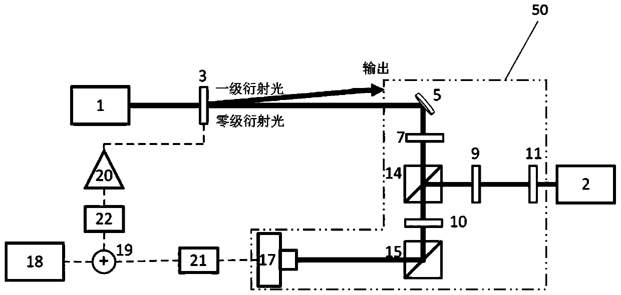
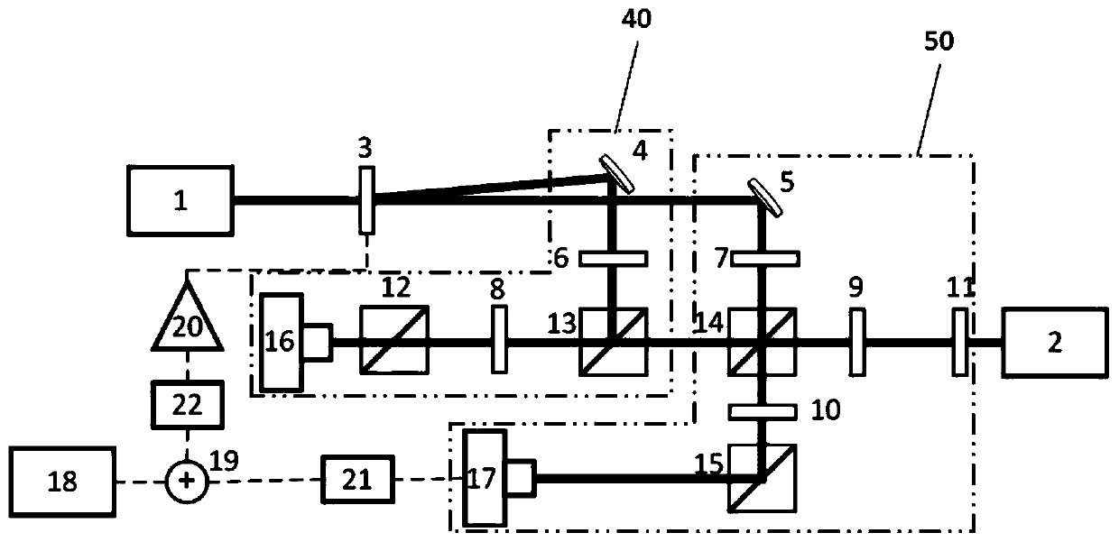
[0041] This embodiment provides a continuous light-optical frequency comb locking device, see figure 1 , which includes:

[0042] Continuous laser 1, the continuous laser 1 is a monolithic solid-state ring laser with Nd:YAG crystal as the gain medium, and the output laser wavelength is 1064nm. In this embodiment, a pre-stabilization unit is provided inside the CW laser, which includes a frequency doubler, and part of the 1064nm CW light is frequency-doubled to 532nm and stabilized with iodine molecular saturation absorption, and then controlled by the cavity length of the laser resonator and The temperature of the gain medium achieves the effect of frequency stabilization. After frequency stabilization, the jitter of the continuous laser and the beat frequency signal of the optical frequency comb mentioned later is tens of kHz.

[0043] Optical frequency comb 2, the optical frequency comb 2 is an ytterbium-doped fiber optical frequency comb, locked to a semiconductor continuo...

no. 2 example

[0071] This embodiment provides another continuous light-optical frequency comb locking device, see Figure 7 , in this embodiment, a fiber-optic bandpass filter 32, fiber polarization controllers 29 and 31, a fiber combiner 26 and a photodetector 17 are used to form a fiber-optic coherent heterodyne beating device 70. Specifically, the zero-order diffracted light output from the acousto-optic frequency shifter 3 is coupled into an optical fiber through a fiber coupler 24 . The optical frequency comb 2 is provided with an optical fiber output port, the output light is filtered by the optical fiber bandpass filter 32 and the polarization adjustment of the optical fiber polarization controller 31, and the zero-order diffraction of the polarization direction is adjusted by the optical fiber polarization controller 29 The light is combined in the fiber beam combiner 26 and connected to the photodetector 17, and then the beat frequency electrical signal output by the photodetector ...


PUM


Abstract

The invention provides a continuous optical-optical frequency comb locking device and locking device that includes a continuous laser source for emitting continuous light; An optical frequency comb having a frequency range covering the frequency of the continuous light; Acousto-optic frequency shifter means for dividing the continuous light into zero-order diffracted light and first-order diffracted light; Coherent heterodyne beat means for obtaining beat signals of the zero-order diffracted light and the optical frequency comb; And a pre-feedback unit that feeds the beat frequency signal back to the acousto-optic frequency shifter device to lock the first order diffracted light to the optical frequency comb.

Description

technical field [0001] The invention belongs to the field of laser technology, and in particular relates to a continuous light-optical frequency comb locking device and a locking method. Background technique [0002] In laser technology research, optical frequency combs pursue ultra-wide spectrum and narrow pulse width, while frequency-stabilized lasers pursue extremely narrow spectrum. The combination of the two becomes an important tool for researching frequency standards and high-precision measurement. In order to improve the stability of the optical frequency comb and narrow the linewidth of the teeth of the optical frequency comb, the optical frequency comb is usually locked to the ultra-stable laser with a very narrow linewidth, so that the stability of the ultra-stable laser is transferred to the optical frequency comb on each comb tooth. Conversely, for a CW laser whose parameters such as frequency stability and line width are not as good as an optical frequency com...

Claims


Application Information

Patent Timeline
Patent Type & Authority Patents(China)
IPC IPC(8): H01S3/098
CPCH01S3/1109
Inventor 邵晓东韩海年张子越汪会波魏志义
Owner INST OF PHYSICS - CHINESE ACAD OF SCI
Learn More