A laser power monitoring system and monitoring method

A laser power and laser technology, which is applied in the direction of the device for controlling the output parameters of the laser, and can solve the problems of large error, large space occupation, and complex control interface.

Inactive Publication Date: 2019-01-15
GUANGDONG TECHN COLLEGE OF WATER RESOURCES & ELECTRIC ENG
View PDF6 Cites 7 Cited by
  • Summary
  • Abstract
  • Description
  • Claims
  • Application Information

AI Technical Summary

Problems solved by technology

[0005] The power control process of existing lasers generally involves the switching control of the main oscillator switch signal, modulation input switch signal, parallel signal, etc., in which the signal transmission line generally uses 9 lines to transmit power data and control data. The interface is relatively complicated, and on the other hand, due to the complicated process of data transmission and control through multiple lines,

Method used


Image

  • A laser power monitoring system and monitoring method
  • A laser power monitoring system and monitoring method
  • A laser power monitoring system and monitoring method

Examples


Embodiment Construction

[0115] In order to make the object, technical solution and advantages of the present invention more clear, the present invention will be further described in detail below in conjunction with the examples. It should be understood that the specific embodiments described here are only used to explain the present invention, not to limit the present invention.

[0116] The application principle of the present invention will be further described below in conjunction with the accompanying drawings and specific embodiments.

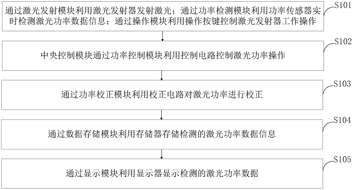
[0117] Such as figure 1 As shown, a kind of laser power monitoring method provided by the present invention comprises the following steps:

[0118] Step S101, using the laser emitter to emit laser light through the laser emitting module; using the power sensor to detect the laser power data information in real time through the power detection module; using the operation button to control the working operation of the laser emitter through the operation module;

[...


PUM


Abstract

The invention belongs to the technical field of laser power monitoring and discloses a laser power monitoring system and a monitoring method. The laser power monitoring system comprises a laser emission module, a power detection module, an operation module, a central control module, a power control module, a power correction module, a data storage module and a display module. The invention can obtain laser pulses whose laser power varies with the input quantity of the analog input signal through the power control module. Compared with the prior laser pulse power control, the control interfaceis simpler, the control efficiency is higher, and the synchronous control of the laser pulse power can be realized. At that same time, a control current is obtain according to the pow correction module. Laser power curve, the relationship between control current and laser power can be obtained, so that the laser power can be obtained by detecting the control current, and the laser power can be corrected more accurately without adding additional power detection equipment.

Description

technical field [0001] The invention belongs to the technical field of laser power monitoring, and in particular relates to a laser power monitoring system and a monitoring method. Background technique [0002] Light is that after the electrons in the atom absorb energy, they jump from a low energy level to a high energy level, and then fall back from a high energy level to a low energy level. When falling back, the energy released is released in the form of photons. And the laser is the induced (excited) photon queue, the photons in this photon queue have the same optical characteristics, and their steps are extremely consistent. The space control and time control of the laser are very good, and the freedom of the material, shape, size and processing environment of the processing object is very large. It is especially suitable for automatic processing. The combination of laser processing system and computer numerical control technology can constitute efficient automation. ...

Claims


Application Information

Patent Timeline
IPC IPC(8): H01S5/06
CPCH01S5/06
Inventor 曹薇邵忠良黄诚邓桂芳韩琳
Owner GUANGDONG TECHN COLLEGE OF WATER RESOURCES & ELECTRIC ENG
Why Eureka
Try Eureka