Ultrasonic vibration assisted friction welding method
A technology of ultrasonic vibration and friction welding, used in welding equipment, non-electric welding equipment, metal processing equipment, etc., can solve problems such as poor strength of welded joints, and achieve the effect of improving strength, effective connection, and promoting plastic deformation.
- Summary
- Abstract
- Description
- Claims
- Application Information
AI Technical Summary
Problems solved by technology
Method used
Image

Examples
Embodiment 1
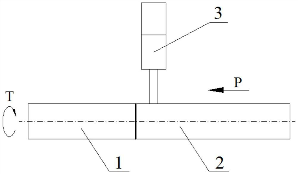
[0024]Example 1: Referencefigure 1 The specific steps of the ultrasonic vibration assisted friction welding method of this embodiment are as follows:
[0025]Step 1. Clamp the rotating end work piece 1 and the moving end work piece 2 respectively on the rotating fixture and the moving fixture of the rotary friction welding machine;
[0026]Step 2. The rotary friction welding machine drives the rotating end workpiece 1 to rotate through the spindle motor and the rotating fixture, and the mobile end hydraulic system drives the mobile end workpiece 2 through the sliding table and the mobile fixture to gradually approach and press on the high-speed rotating rotating end workpiece 1, friction The pressure is 50~350MPa, the friction deformation is 1.0~3.0mm, and the friction time is 3~12s. At the same time, the ultrasonic transducer output head 3 is pressed on the mobile end workpiece 2, and ultrasonic vibration is applied to the mobile end workpiece 2. The frequency is 20-100kHz; when any para...
Embodiment 2
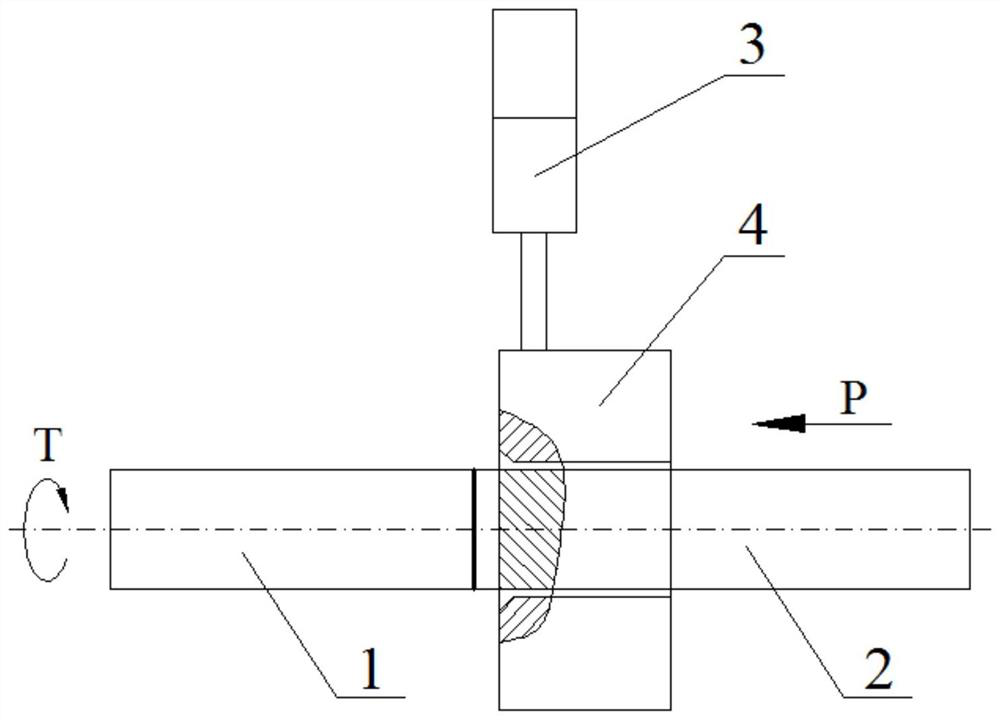
[0027]Example 2: ReferenceFigure 2-3On the basis of embodiment 1, the mobile end workpiece 2 is restricted, and the remaining welding methods are the same. The specific steps of the ultrasonic vibration assisted friction welding method of this embodiment are as follows:
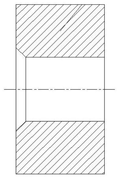
[0028]Step 1. Clamp the rotating end work piece 1 and the moving end work 2 on the rotating fixture and the moving fixture of the rotary friction welding machine respectively, and put the restraint sleeve 4 on the moving end work piece 2, the restraining sleeve 4 and the moving end work piece 2 The gap is 0.2~0.5mm, and the welding surface of the workpiece 2 at the moving end extends out of the restraint sleeve 4 by 4.0~4.2mm;
[0029]Step 2. The rotary friction welding machine drives the rotating end workpiece 1 to rotate through the spindle motor and the rotating fixture, and the mobile end hydraulic system drives the mobile end workpiece 2 through the sliding table and the mobile fixture to gradually approach and pres...
Embodiment 3
[0030]Example 3: ReferenceFigure 4 On the basis of Example 1, the rotary friction welding machine was replaced with a linear friction welding machine, and the rotary clamp was replaced with a vibration clamp. The specific steps of the ultrasonic vibration assisted friction welding method of this embodiment are as follows:
[0031]Step 1. Clamp the vibrating end workpiece 5 and the mobile end workpiece 2 on the vibrating fixture and the mobile fixture of the linear friction welding machine respectively;
[0032]Step 2. The linear friction welding machine drives the workpiece 5 at the vibrating end to vibrate up and down with high frequency and small amplitude through the vibrating end hydraulic system and the vibrating fixture. The vibration frequency is 20-60 Hz and the amplitude is 1 to 3 mm; the mobile end hydraulic system passes through the sliding table and The mobile fixture drives the mobile end workpiece 2 to gradually approach and press on the reciprocating vibration end workpiece...
PUM
 Abstract
Description
Claims
Application Information
 - R&D
- Intellectual Property
- Life Sciences
- Materials
- Tech Scout
- Unparalleled Data Quality
- Higher Quality Content
- 60% Fewer Hallucinations
Browse by: Latest US Patents, China's latest patents, Technical Efficacy Thesaurus, Application Domain, Technology Topic, Popular Technical Reports.
© 2025 PatSnap. All rights reserved.Legal|Privacy policy|Modern Slavery Act Transparency Statement|Sitemap|About US| Contact US: help@patsnap.com