Heat pump system for humidity removing and drying

A technology of heat pump system and hot air system, which is applied in the direction of heat pump, drying, dryer, etc., which can solve the problems of low drying temperature, inability to dehumidify materials at low temperature, and large process differences.

Pending Publication Date: 2019-01-18
JIANGSU TENESUN ELECTRICAL APPLIANCE
View PDF11 Cites 3 Cited by
  • Summary
  • Abstract
  • Description
  • Claims
  • Application Information

AI Technical Summary

Problems solved by technology

There are mainly two types of drying heat pumps on the market, one is hot air dehumidification drying, this drying method is suitable for places that require fast water discharge and high drying temperature; the other is dehumidification drying, Suitable for places with low drying water rate and low drying temperature
[0003] However, because the drying requirements of various materials are very different, and at the same time, during the drying process, the dry and wet bulb temperatures in the air are different in different time periods, and the requirements are different, resulting in customized products that cannot be formed. Batch
[0004] The invention application with the applic

Method used


Image

  • Heat pump system for humidity removing and drying

Examples


Embodiment 1

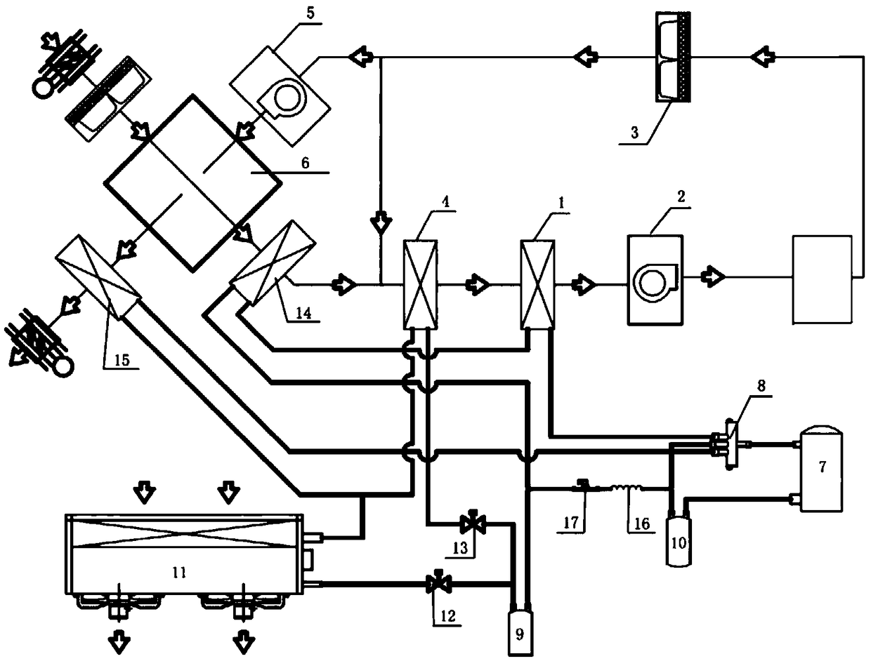
[0144] The structure of this embodiment is as follows: the refrigerant sequentially passes through the compressor-four-way valve-supply air heating condenser-liquid receiver-return air evaporator-four-way valve-vapor-liquid separator-compressor to form a closed refrigeration cycle system The internal refrigerant circulation loop, the hot air discharged through the air outlet of the air supply heating condenser forms the hot air for drying, which is sent into the drying room through the air supply fan; the dried hot air passes through the air outlet of the drying room After being discharged to the first primary filter for filtration, it is then transported to the air inlet of the return air evaporator, through the heat absorption of the return air evaporator, the first dehumidification is completed, and the air after the first dehumidification is sent to the supply air Heating is carried out in the heating condenser to form the first weighting of the basic hot air based on the p...

Embodiment 2

[0146] In this embodiment, on the basis of the structure in Embodiment 1, a secondary dehumidification system is added, and the secondary dehumidification system is arranged in parallel from the air outlet of the first primary effect filter (3) of the primary dehumidification system to the return air evaporator ( 4) On the pipeline of the air inlet, it is used to form the second weighting of the basic hot air based on the secondary dehumidification,

[0147] With the first weighted cooperation provided by the primary dehumidification system, it can provide separate primary dehumidification, separate secondary dehumidification, primary dehumidification and secondary dehumidification cooperation, and three dehumidification working modes. The separate primary dehumidification is used for low humidity dehumidification requirements; Separate secondary dehumidification is used for high humidity dehumidification needs; the primary dehumidification is coordinated with secondary dehumid...

Embodiment 3

[0158] In this embodiment, on the basis of the structure of Embodiment 2, a heat recovery evaporator (15) is added,

[0159] The heat recovery evaporator (15) is arranged at the second air outlet of the total heat heat exchanger (6). Compared with embodiment 2, this embodiment has more heat recovery evaporators, and the heat recovery evaporators are used to convert The residual air after heat exchange discharged through the second air outlet of the total heat heat exchanger (6) is subjected to heat recovery treatment to reinforce the heating capacity of the primary hot air system; the system after adding a heat recovery evaporator;

[0160] Further, the pipeline structure connected to the refrigerant inlet of the heat recovery evaporator (15) has the following characteristics: the pipeline connected to the refrigerant outlet of the return air evaporator (4) and the refrigerant connected to the outdoor evaporator (11) The pipes at the outlet end are connected in parallel; the h...


PUM


Abstract

The invention discloses a heat pump system for humidity removing and drying. The system is used for providing hot air required by drying of a drying room. The system comprises an arranged primary hotair system, the primary hot air system outputs basic hot air through an air supplying heating condenser arranged in the system, and the basic hot air is conveyed to the drying room through an air supplying draught fan arranged in the primary hot air system; hot air exhausted from an air outlet of the drying room is filtered by a first primary filter arranged in the primary hot air system and conveyed to an air inlet of an air-returning evaporator arranged in the primary hot air system through a pipeline and an air inlet of an air supplying heating condenser through an air outlet pipeline of anair-returning evaporator, and first weighting for basic hot air is formed after primary humidity removing. Air-returning humidity removing, heating for new air, overheating of a compressor in air sucking process and transferring of outside free heat the drying room are achieved to meet the requirements of variable working conditions of high-low temperature and high-low humidity in the drying room.

Description

technical field [0001] The invention belongs to the field of hot air drying, and in particular relates to a heat pump system for dehumidification and drying. Background technique [0002] At present, there are more and more places that need hot air drying in the market, such as tobacco drying, grain drying, medicinal materials drying, fruit and vegetable drying and other drying places. Coal furnaces, gas furnaces and electric furnaces are mainly used for drying. Coal and gas are non-renewable strategic energy sources, which are not the direction of national promotion. Electric furnaces are not suitable for mass promotion because of their high energy consumption and high operating costs. Due to the many reasons mentioned above, heat pump dryers are now gradually being accepted by the market because of their many advantages such as energy saving, environmental protection, and high drying quality. There are two main types of drying heat pumps on the market, one is hot air dehu...

Claims


Application Information

Patent Timeline
IPC IPC(8): F26B21/00F25B30/02
CPCF25B30/02F26B21/002F26B21/003
Inventor 王天舒王玉军吴小网李柱刘军王颖
Owner JIANGSU TENESUN ELECTRICAL APPLIANCE
Why Eureka
Try Eureka