
Combined heat and carbon dioxide supply system for greenhouse

A carbon dioxide and greenhouse technology, applied in the field of greenhouse agriculture, can solve the problems of unstable wind power generation, unstable system, and high thermal efficiency, and achieve the effects of facilitating purification and dust removal, realizing automation, and improving initial temperature.

Inactive Publication Date: 2019-01-25
JIANGSU UNIV
View PDF14 Cites 5 Cited by
  • Summary
  • Abstract
  • Description
  • Claims
  • Application Information

AI Technical Summary

Problems solved by technology

The Chinese patent application number is 201220436323.1 patented greenhouse and greenhouse heating boiler. The specification discloses a greenhouse and greenhouse heating boiler. High thermal efficiency; but only a new type of greenhouse boiler is disclosed, and there is no excessive design for the greenhouse heating system, and there are no carbon dioxide supply measures
Another example is the Chinese patent application number 201620764097.8, which uses wind energy to supply power to the greenhouse of the heating boiler. The specification discloses a greenhouse that uses wind energy to supply power to the heating boiler. Water boilers combined with heat storage materials solve the problem of unstable wind power generation; however, due to the instability of wind energy, the entire system is unstable, and the increase in heat storage materials greatly increases the initial and maintenance costs of the system, which is not conducive to Application and promotion
Therefore, there is a large gap in technology or patents in the field of greenhouse combined heating and carbon dioxide supply in my country

Method used


Image

  • Combined heat and carbon dioxide supply system for greenhouse
  • Combined heat and carbon dioxide supply system for greenhouse

Examples


Embodiment Construction

[0024] The present invention will be further described below in conjunction with the accompanying drawings and specific embodiments, but the protection scope of the present invention is not limited thereto.

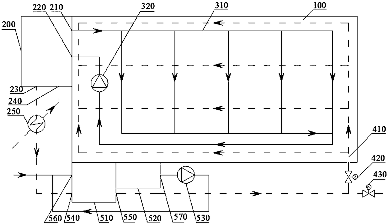
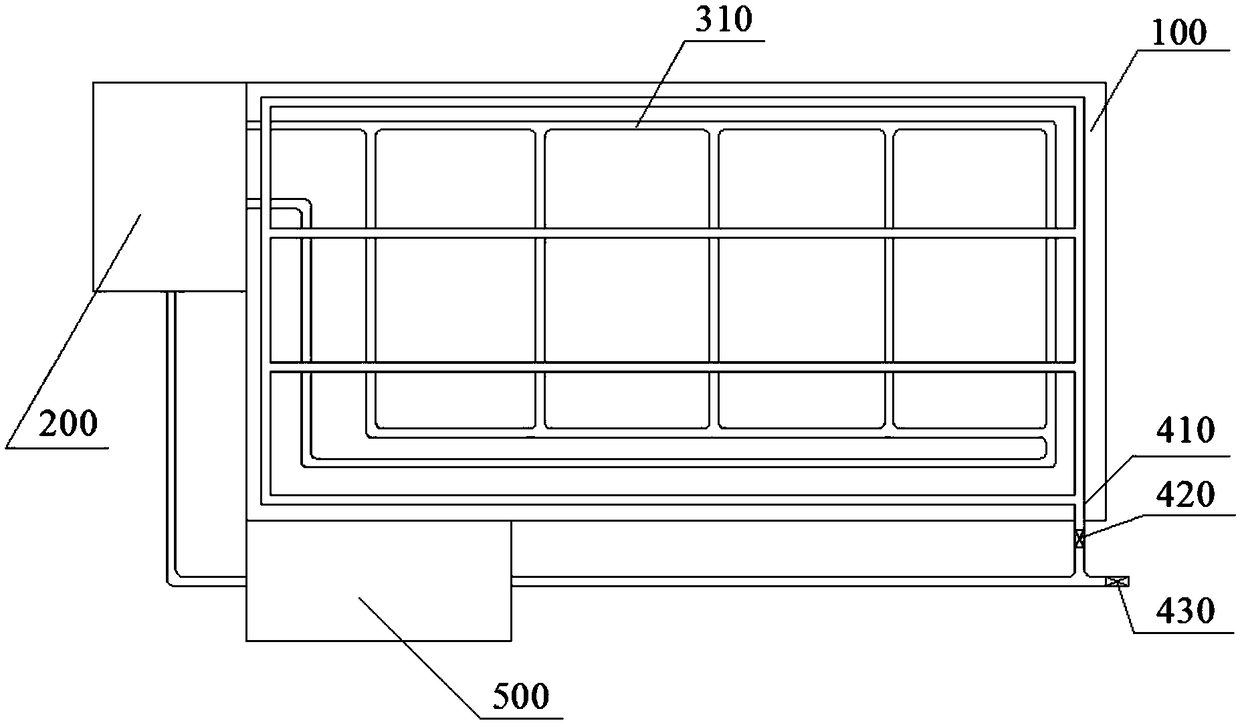
[0025] Such as figure 1 and figure 2 As shown, a greenhouse combined heating and carbon dioxide supply system includes a biomass boiler 200, a heat exchanger 250, a gas purification room 500 and a control system; the biomass boiler 200 is provided with a steam outlet 210 and a liquid water inlet 220 and the flue gas outlet 230, the inside of the greenhouse 100 is provided with a closed-loop heating pipe 310, and the steam outlet 210 is sequentially connected to the return pump 320 and the liquid water inlet 220 through the heating pipe 310; the inside of the greenhouse 100 is provided with a carbon injection pipe 410 , the flue gas outlet 230 is sequentially connected with the heat exchanger 250 , the gas cleaning chamber 500 and the carbon injection tube 410 . The car...


PUM


Abstract

The invention provides a combined heat and carbon dioxide supply system for a greenhouse. The system comprises a biomass boiler, a heat exchanger and a gas purifying room, wherein a steam outlet, a liquid water inlet, a smoke outlet and an air inlet are formed in the biomass boiler, the greenhouse is internally provided with a heat supply pipe and a carbon dioxide spraying pipe, the heat supply pipe is in closed-loop connection with the steam outlet and the liquid water inlet, the smoke outlet is connected with the heat exchanger, the gas purifying room and the carbon dioxide spraying pipe insequence, and the air inlet is connected with an outlet of the heat exchanger. The gas purifying room comprises a water-bath dust remover, a sedimentation tank and a water supply pump; an air inlet and an air outlet are formed in the water-bath dust remover, and the water-bath dust remover is communicated with the bottom of the sedimentation tank; a water outlet of the sedimentation tank is in closed-loop connection with the water supply pump and a water inlet of the water-bath dust remover in sequence; the air outlet is connected with the carbon dioxide spraying pipe. The greenhouse is heatedby steam generated by the biomass boiler, and smoke is purified and then provides carbon dioxide for the greenhouse.

Description

technical field [0001] The invention relates to the field of greenhouse agriculture, in particular to a greenhouse combined heating and carbon dioxide supply system. Background technique [0002] In most parts of our country, the winter is severe and long. In the cold winter and spring seasons when crops cannot grow, it is the only way to vigorously develop greenhouse vegetable production. Through the construction of various greenhouses, some vegetable supply problems in winter and spring cold seasons have been solved. At present, all kinds of greenhouses are mainly to increase the temperature in the greenhouse, but to increase the yield of vegetables, it is not enough to only increase the temperature in the vegetable greenhouse. According to the principle of photosynthesis, photosynthesis is the process in which green plants use light energy to convert carbon dioxide and water into organic matter that stores energy and release oxygen through chloroplasts. The optimum tempe...

Claims


Application Information

Patent Timeline
Patent Type & Authority Applications(China)
IPC IPC(8): A01G9/24A01G9/18F22B31/00F23J15/04
CPCA01G9/18A01G9/24F22B31/00F23J15/04F23J2217/50Y02A40/25
Inventor 吉恒松宋浩仲敏波戚奕周言姚勇
Owner JIANGSU UNIV
Learn More