
Apparatus and method for preparing ice particle gas jet from supercooled water

A technology of gas jet and supercooled water, which is applied in the direction of used abrasive processing devices, explosion generating devices, and equipment that generates abrasive jets in a non-mechanical way, and can solve problems such as unsuitable control, large energy consumption, and stickiness , to achieve the effect of reducing the cost of jet operation, improving efficiency and precision, and uniform shape and size

Pending Publication Date: 2019-01-25
HENAN POLYTECHNIC UNIV
View PDF1 Cites 1 Cited by
  • Summary
  • Abstract
  • Description
  • Claims
  • Application Information

AI Technical Summary

Problems solved by technology

[0002] Gas abrasive jet has been widely used in various industries since its invention because of its simple structure, low energy consumption, and good erosion effect. It is used to erode and break coal; however, with the wide application of gas jet, its disadvantages are gradually appearing. Since the abrasives are mostly materials with high hardness and high density, it is inevitable to It will cause certain damage to the internal material, and there is no suitable substitute abrasive; at the same time, in some large projects, the amount of abrasive is huge. On the one hand, the abrasive cannot be recycled, resulting in a large waste. On the other hand, the abrasive is broken into Tiny respirable dust and suspended particles will inevitably deteriorate the working environment and affect the health of the staff; therefore, researchers from various countries are constantly looking for substitutes for ordinary abrasives; the Mohs hardness of ice at different temperatures varies from 2- 4. The hardness is moderate, which can remove the paint and rust on the surface without damaging the internal components. At the same time, the ice particles will not deteriorate the working environment and cause health threats to the staff after being sprayed out, so the ice particles can be used as a substitute for traditional gas jet abrasives product made possible
[0003] At present, there are three main methods for preparing ice particles: (1) Ice breaking method, that is, using a mechanical device to crush large pieces of ice into small particles. The particle size is used, which reduces the preparation speed of ice particles, and it is not easy to store ice particles; (2) low-temperature freezing method, spray water mist into a space with low-temperature nitrogen (liquid nitrogen), and the water mist freezes quickly to form Ice particles, this method prepares ice particles quickly, but due to the direct contact between liquid droplets and low-temperature nitrogen (liquid nitrogen), the temperature of ice particles drops rapidly, and it is not suitable for control, making it difficult to control the hardness of ice particles; at the same time, the structure of the device is complicated , cumbersome operation, and high energy consumption; (3) Liu Yong and others disclosed "a device and method for rapid preparation of ice particle gas jet", application number 201611113564.1, which uses atomizing nozzles to spray atomized droplets into the high-speed airflow, and then the liquid droplets are in contact with the mixed gas of liquid nitrogen and air. This method makes up for the shortcomings of the cryogenic freezing method. The temperature of the mixed gas of liquid nitrogen and air is suitable, and the hardness of the ice particles is easier to adjust, but it is also There are certain problems, such as the liquid droplets do not change phases in time, they are easy to merge and merge to form larger droplets, and the droplets will stick to the pipe wall, causing the effective diameter of the pipe to decrease after freezing, which is easy to block

Method used


Image

  • Apparatus and method for preparing ice particle gas jet from supercooled water
  • Apparatus and method for preparing ice particle gas jet from supercooled water

Examples


Embodiment Construction

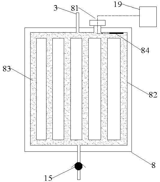
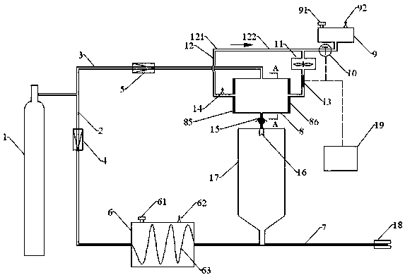
[0027] Such as figure 1 and figure 2 A device for preparing ice particle gas jets using supercooled water is shown, including air flow circulation 12, wherein the air flow circulation 12 is connected to the high-pressure gas cylinder 1 through the second branch pipeline 3, and is connected to the mist in the atomization chamber 17 through the pipeline 121. The atomization nozzle 16 is connected, wherein the bottom end of the atomization chamber 17 is connected with the confluence pipe 7, one end of the confluence pipe 7 is connected with the first liquid nitrogen tank 6, and the other end is connected with the nozzle 18, and the first liquid nitrogen tank 6 passes through the first branch pipeline 2. Connect with the high-pressure gas cylinder 1, wherein the wind flow circulation 12 includes the second liquid nitrogen tank 9, the bottom of the second liquid nitrogen tank 9 is connected with a pipeline 121, one end of the pipeline 121 is connected with the fan 11 through a tee...


PUM


Abstract

A method for preparing ice particle gas jet from supercooled water includes the steps of (1), preparing supercooled water; (2), preparing ice particles and completing gas jet; (3), recycling raw materials. The invention further provides an apparatus for preparing ice particle gas jet from supercooled water, comprising a high-pressure air bottle connected with an air current circulating system through a second branch pipeline, wherein the high-pressure air bottle is connected with a first liquid nitrogen box through a first branch pipeline, the other end of the first liquid nitrogen box is connected with a nozzle through a manifold, an atomizing box is arranged on the manifold between the first liquid nitrogen box and the nozzle, the air current circulating system comprises a heat exchanger, the upper end of the heat exchanger is connected with the second branch pipeline, the left end of the heat exchanger is connected with the second liquid nitrogen box and an air blower through a pipeline and a tee joint, the other end of the heat exchanger is connected with the right end of a heat exchange box, and the bottom of the heat exchange box is connected with an atomizing nozzle of the atomizing box through a pipeline. With the apparatus and the method, ice particles can be prepared and ice particle gas jet can be formed rapidly.

Description

technical field [0001] The invention relates to the technical field of ice particle gas jet, in particular to a device and method for preparing ice particle gas jet by using supercooled water. Background technique [0002] Gas abrasive jet has been widely used in various industries since its invention because of its simple structure, low energy consumption, and good erosion effect. It is used to erode and break coal; however, with the wide application of gas jet, its disadvantages are gradually appearing. Since the abrasives are mostly materials with high hardness and high density, it is inevitable to It will cause certain damage to the internal material, and there is no suitable substitute abrasive; at the same time, in some large projects, the amount of abrasive is huge. On the one hand, the abrasive cannot be recycled, resulting in a large waste. On the other hand, the abrasive is broken into Tiny respirable dust and suspended particles will inevitably deteriorate the wo...

Claims


Application Information

Patent Timeline
IPC IPC(8): B24C5/08B24C9/00
CPCB24C5/08B24C9/00
Inventor 魏建平张路路刘勇张宏图徐向宇姜婉任永婕
Owner HENAN POLYTECHNIC UNIV
Learn More