Electrochemical device for preparing hydrogen peroxide and application thereof

A hydrogen peroxide and electrochemical technology, applied in chemical instruments and methods, oxidized water/sewage treatment, electrodes, etc., can solve the problems of unsustainable supply of hydrogen peroxide and difficult engineering applications

Pending Publication Date: 2019-01-29
HARBIN INST OF TECH
View PDF0 Cites 8 Cited by
  • Summary
  • Abstract
  • Description
  • Claims
  • Application Information

AI Technical Summary

Problems solved by technology

[0003] The present invention proposes an electrochemical device for preparing hydrogen peroxide in order to solve the problem that the existing hydrogen peroxide preparation device is an intermittent flow device or a static container, which cannot continuously provide hydrogen peroxide and is difficult to carry out engineering applications widely. and applications

Method used


Image

  • Electrochemical device for preparing hydrogen peroxide and application thereof
  • Electrochemical device for preparing hydrogen peroxide and application thereof
  • Electrochemical device for preparing hydrogen peroxide and application thereof

Examples


specific Embodiment approach 1

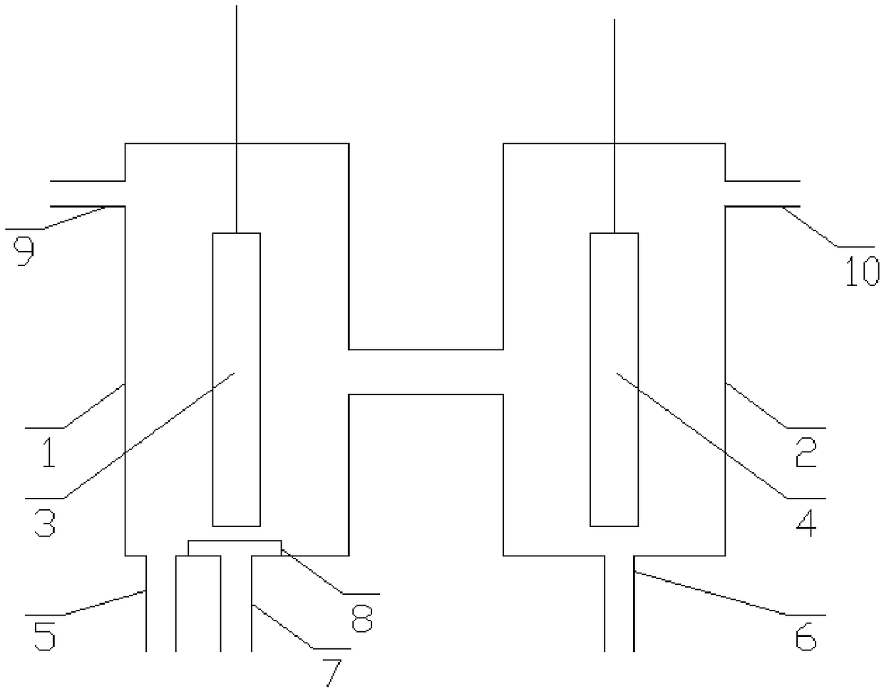
[0018] Specific implementation mode one: combine figure 1 Describe this embodiment, the electrochemical device for preparing hydrogen peroxide in this embodiment is composed of cathode chamber 1, anode chamber 2, cathode 3 and anode 4;

[0019] The cathode chamber 1 and the anode chamber 2 are arranged side by side, and the side of the cathode chamber 1 and the side of the anode chamber 2 are connected through pipelines; the cathode 3 and the anode 4 are flat plates, the cathode 3 is vertically arranged in the cathode chamber 1, and the anode 4 is vertically arranged It is arranged in the anode chamber 2; the bottom of the cathode chamber 1 is provided with a cathode chamber water inlet pipe 5 and an oxygen inlet pipe 7; the cathode chamber 1 is provided with a gas distribution chamber 8 below the cathode 3, and the top surface of the gas distribution chamber 8 is a porous plate; The bottom surface of 3 is arranged towards the midline of the top surface of gas distribution cha...

specific Embodiment approach 2

[0026] Embodiment 2: This embodiment is different from Embodiment 1 in that: the inlet end of the oxygen inlet pipe 7 communicates with the gas outlet of the oxygen generator. Other steps and parameters are the same as those in the first embodiment.

specific Embodiment approach 3

[0027] Specific embodiment three: this embodiment is different from specific embodiment one or two in that: the cathode 3 is connected to the negative pole of the power supply through a wire; the anode 4 is connected to the positive pole of the power supply through a wire; 10mA / cm 2 ; The minimum current density applied to the anode 4 is 10mA / cm 2 . Other steps and parameters are the same as those in Embodiment 1 or 2.


PUM

PropertyMeasurementUnit
volumeaaaaaaaaaa

Abstract

The invention relates to an electrochemical device for preparing hydrogen peroxide and an application thereof. The purpose is to solve the problem that hydrogen peroxide preparation device cannot provide hydrogen peroxide continuously and cannot be widely used in engineering due to batch flow device or static standing container. The device consists of a cathode chamber, an anode chamber, a cathodeand an anode. The cathode chamber side is communicated with the anode chamber side; a gas distribution chamber is arranged below the cathode in the cathode chamber, and the top surface of the gas distribution chamber is a porous plate; the bottom surface of the cathode is arranged toward the middle line of the top surface of the air distribution chamber; the cathode material is graphene doped carbon foam or carbon nitride doped carbon foam. The invention improves the efficiency of hydrogen peroxide preparation and is beneficial to stabilizing the concentration of hydrogen peroxide by doping carbon foam with graphene or carbon nitride; the device of the invention can stably and continuously generate hydrogen peroxide under low current density. The device of the invention is applied in wastewater treatment and microbial inactivation. The invention is suitable for preparing hydrogen peroxide.

Description

technical field [0001] The invention relates to an electrochemical device and application for preparing hydrogen peroxide. Background technique [0002] Hydrogen peroxide is widely used as an oxidant in wastewater treatment and microbial inactivation devices. In the research of ultraviolet radiation and photocatalytic microbial inactivation, the presence of hydrogen peroxide can greatly improve the efficiency of microbial inactivation. Therefore, in recent years, electric Chemical in-situ generation of hydrogen peroxide to enhance the inactivation of microorganisms. The commonly used preparation methods of hydrogen peroxide include photocatalytic method, electrochemical synthesis method and so on. The problem existing in the electrochemical synthesis method is: the existing hydrogen peroxide preparation device is an intermittent flow device or a static container, the intermittent flow device can only produce the hydrogen peroxide solution of the intermittent flow, and canno...

Claims


Application Information

Patent Timeline
Patent Type & Authority Applications(China)
IPC IPC(8): C02F1/72C02F1/50C25B1/30C25B1/26C25B9/06C25B11/06C25B9/17
CPCC25B1/26C25B1/30C25B11/04C02F1/50C02F1/722C02F2305/02C25B9/17
Inventor 赵丽娜尤宏
Owner HARBIN INST OF TECH
Why Eureka
Try Eureka