
Permanent magnet synchronous motor with magnetism concentration effect

A permanent magnet synchronous motor, effect technology, applied to synchronous motors with stationary armatures and rotating magnets, magnetic circuits, electric components, etc., can solve problems such as increased maintenance difficulty, long distributed winding ends, and increased number of stator slots , to achieve the effect of improving torque density and operating efficiency, improving fault tolerance, and avoiding short circuit between phases

Pending Publication Date: 2019-01-29
NORTH CHINA ELECTRIC POWER UNIV (BAODING)
View PDF0 Cites 6 Cited by
  • Summary
  • Abstract
  • Description
  • Claims
  • Application Information

AI Technical Summary

Problems solved by technology

However, in low-speed applications, the shortcomings of the traditional one-piece stator core integer slot distributed winding permanent magnet motor gradually become prominent
This kind of motor has a large number of poles, which increases the number of stator slots, which increases the difficulty of design and processing. In addition, the end of the distributed winding is longer, resulting in a higher amount of copper and an increase in interphase insulation materials. The dosage and the copper consumption when the motor is running
With the increase of the single unit capacity of the traditional motor, the difficulty of transportation, assembly and maintenance of the motor will gradually increase. At the same time, the motor will have a larger volume, which will increase the iron consumption of the motor during operation and reduce the operating efficiency of the motor. Therefore it is necessary to improve

Method used


Image

  • Permanent magnet synchronous motor with magnetism concentration effect
  • Permanent magnet synchronous motor with magnetism concentration effect
  • Permanent magnet synchronous motor with magnetism concentration effect

Examples


Embodiment Construction

[0025] The invention proposes a portable permanent magnet synchronous motor with "magnetism gathering" effect. The motor adopts a block-type stator core, which can improve the torque density and operating efficiency of the motor, and at the same time make the motor easy to transport, install and manufacture. and maintenance purposes.

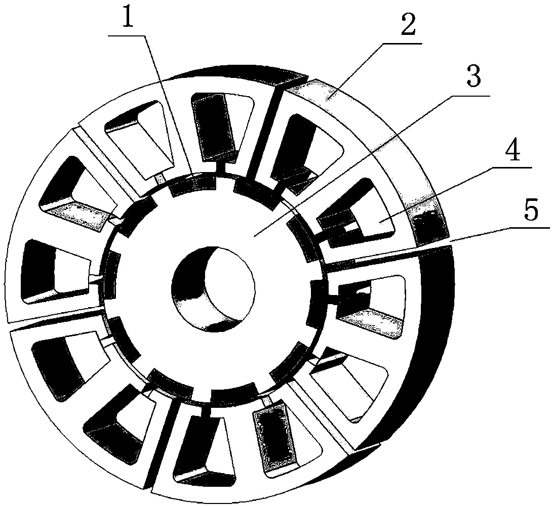
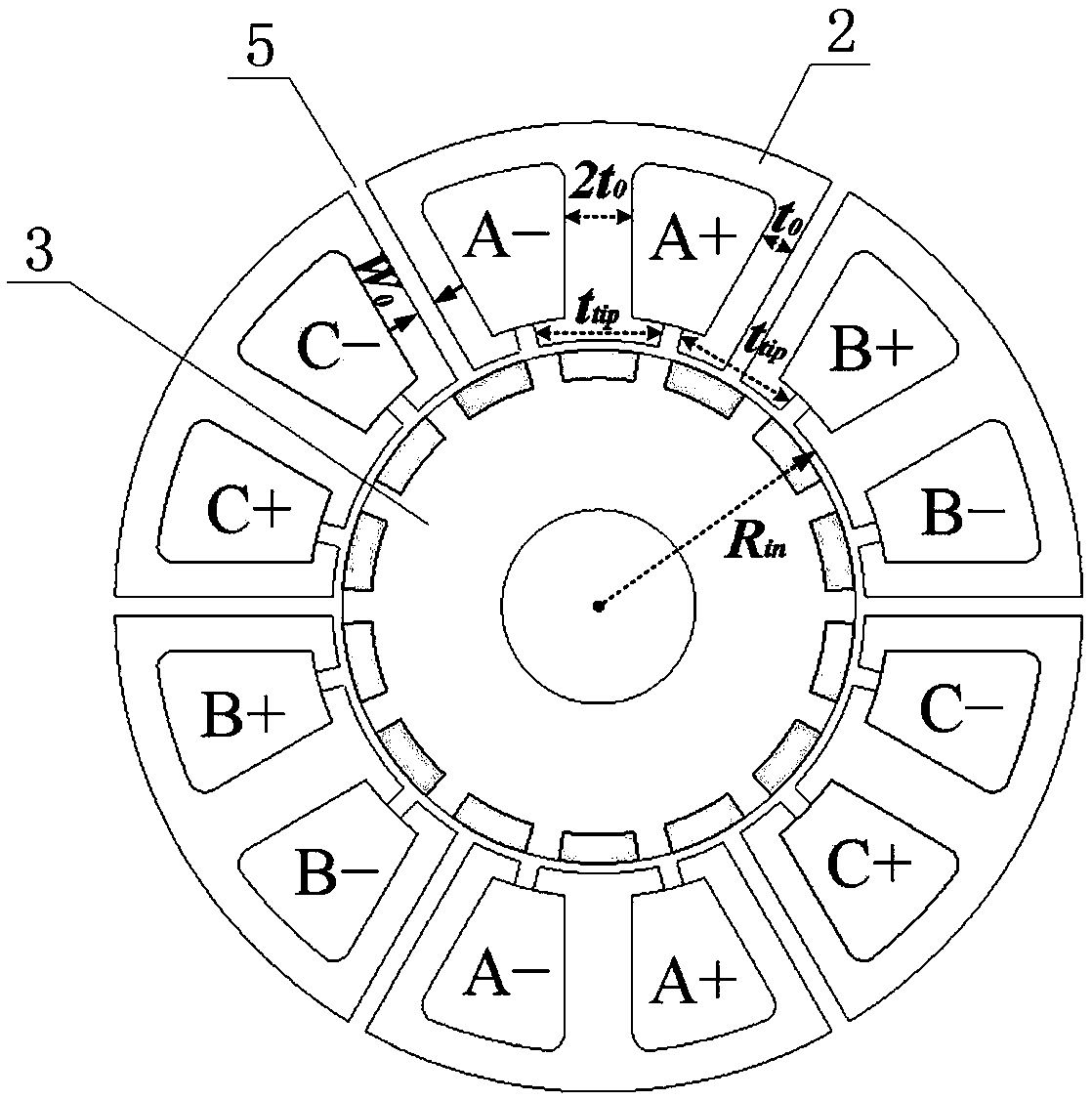
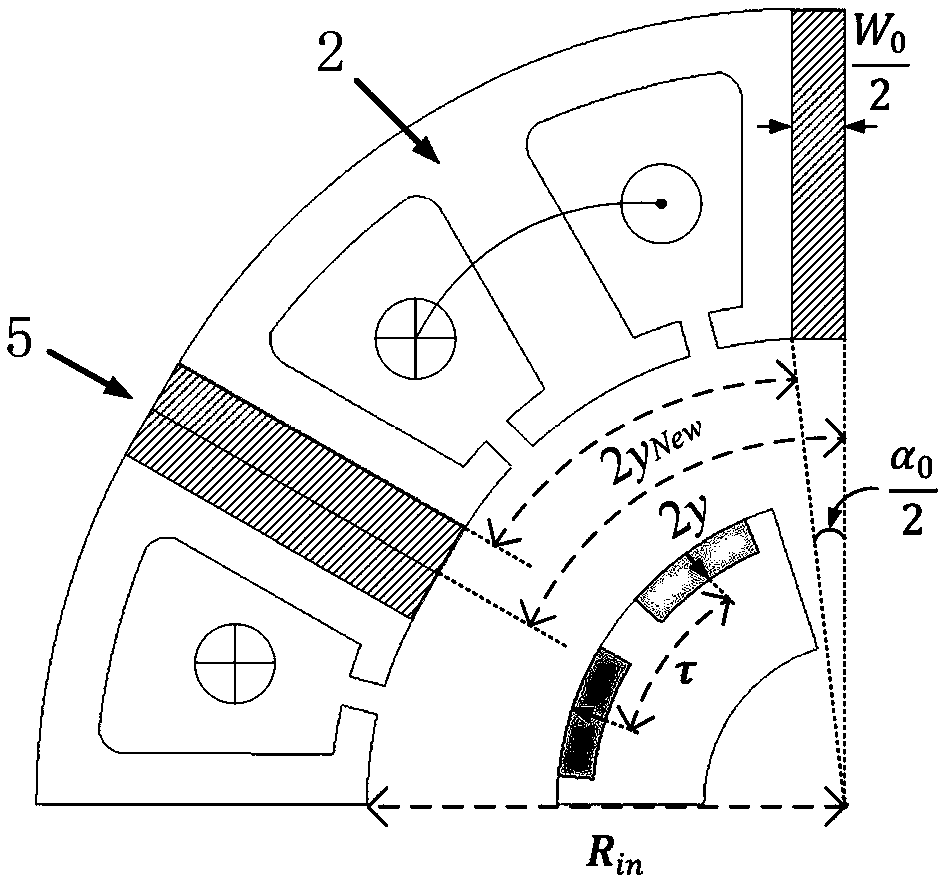
[0026] The present invention provides a novel permanent magnet synchronous motor aiming at few slots and multiple poles, such as figure 1 As shown, the motor completes the transformation of the traditional one-piece fractional slot concentrated winding motor stator by inserting the stator gap into the non-winding teeth. The block stator core and winding configuration are as follows figure 2 shown. Taking the 12-slot and 14-pole segmented stator core motor as an example, keep the width of the winding teeth and their tooth tops unchanged, where the width of the winding teeth is 2t 0 , the winding tooth tip width is t tip , the insertion width...


PUM


Abstract

The invention relates to a permanent magnet synchronous motor with a magnetism concentration effect, which comprises a stator and a rotor, wherein the stator includes a spliced stator core and a stator winding, the spliced stator core is an annular body composed of a plurality of sub-cores uniformly distributed around the rotor, two adjacent sub-cores are provided with a stator gap therebetween, each sub-core is provided with two wire slots at the side opposite to the rotor, the part between the two wire slots of the same sub-core form a winding tooth, the top of the winding tooth and the topof the non-winding tooth are the same in width, and the tooth width of the non-winding tooth is equal to the sum of the tooth width of the winding tooth and the width of the stator gap. The permanentmagnet synchronous motor adopts the spliced stator core, thereby not only simplifying the motor structure, reducing the transportation, installation and maintenance difficulty, but also being capableof avoiding a short circuit between phases and improving the fault-tolerant ability of the motor. The spliced stator core also improves the winding factor and generates a magnetism concentration effect, thereby improving the torque density and operation efficiency of the motor.

Description

technical field [0001] The invention relates to a portable permanent magnet synchronous motor with strong fault tolerance, high torque density and high operating efficiency, belonging to the technical field of synchronous generators. Background technique [0002] High-performance permanent magnet synchronous motors have received more and more attention in the field of industrial engineering due to their advantages of small size, torque density and high operating efficiency. With the emergence of new permanent magnet materials and the continuous development of large permanent magnet motor manufacturing technology in recent years, the stand-alone capacity of permanent magnet motors has continued to increase. However, in low-speed applications, the shortcomings of the traditional one-piece stator core integer slot distributed winding permanent magnet motor gradually become prominent. This kind of motor has a large number of poles, which increases the number of stator slots, wh...

Claims


Application Information

Patent Timeline
IPC IPC(8): H02K21/16H02K1/14H02K1/16H02K1/20H02K1/27
CPCH02K1/148H02K1/16H02K1/165H02K1/20H02K1/2706H02K21/16H02K2213/03
Inventor 王艾萌郭嘉宇
Owner NORTH CHINA ELECTRIC POWER UNIV (BAODING)
Learn More