Method for exciting conductive material to ignite by inputting and outputting electronic from side of circuit board

An electronic excitation, input and output technology, applied in the direction of weapon accessories, fuzes, offensive equipment, etc., can solve problems such as high risk, poor contact, and bridge wires do not have welding melting power, so as to improve the safety and reliability of high temperature resistance and shock resistance. Accuracy, improving efficiency and reliability, and reducing labor costs

Pending Publication Date: 2019-02-01
赵伽文
View PDF4 Cites 3 Cited by
  • Summary
  • Abstract
  • Description
  • Claims
  • Application Information

AI Technical Summary

Problems solved by technology

[0004] 1. The production is unsafe: the ignition powder is composed of gunpowder, which is flammable, easy to catch fire due to collision and friction, the production process of the powder should have high precautionary measures, and the raw materials are flammable and explosive, whether manual or automatic. There is a high risk of head assembly
[0005] 2. Insufficient precision: Both the thermal effect of the bridge wire and the ignition energy of the powder head have a time difference in the heating and burning process. Due to the difference in time delay, it cannot meet the requirements of high-precision and safe ignition energy, and the b

Method used


Image

  • Method for exciting conductive material to ignite by inputting and outputting electronic from side of circuit board
  • Method for exciting conductive material to ignite by inputting and outputting electronic from side of circuit board
  • Method for exciting conductive material to ignite by inputting and outputting electronic from side of circuit board

Examples


Embodiment 1

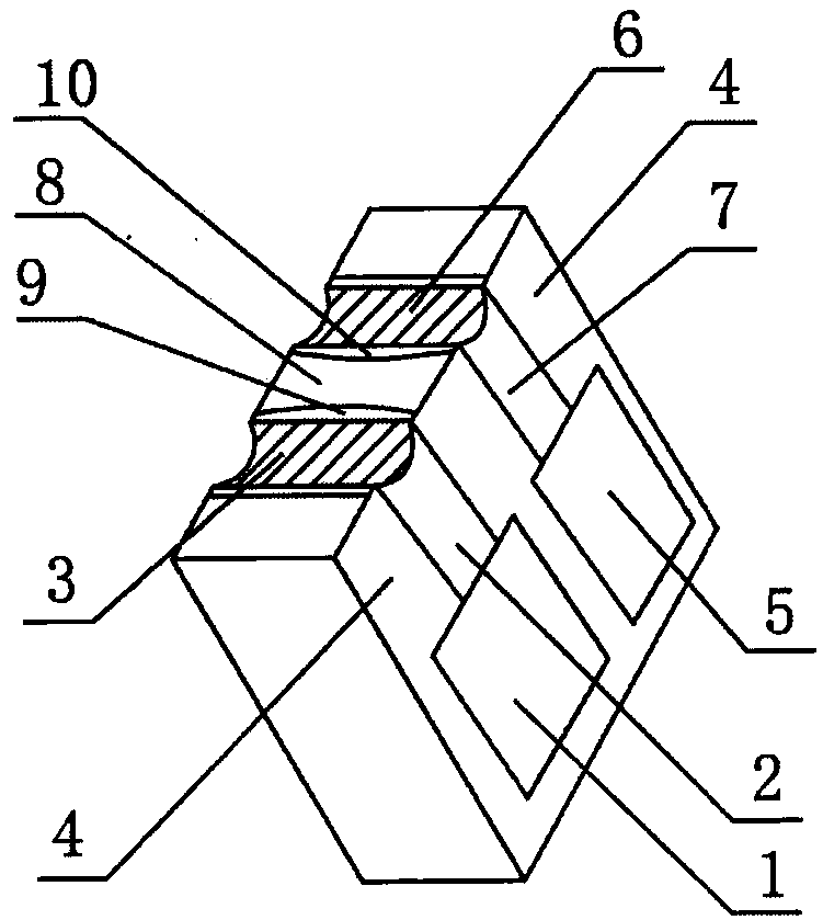
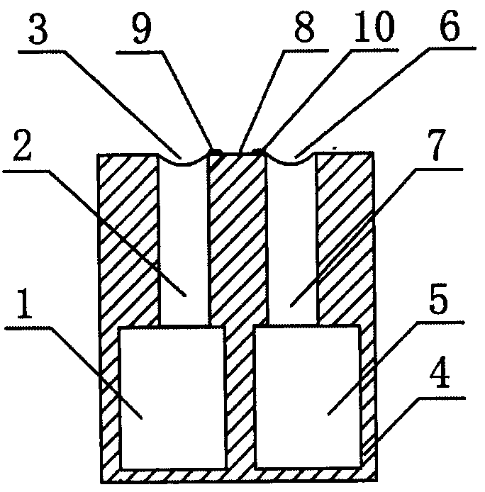
[0034] According to the invention, the input and output electrons on the side of the circuit board excite the ignition of the conductive material. The device involved in the method consists of a PCB circuit board, a first pad electrode 1, a first circuit 2, a first conductive hole 3, and an insulating area. 4. The second pad electrode 5, the second conductive hole 6, the second circuit 7, the discharge area 8, the first discharge terminal 9, the second discharge terminal 10 and the conductive material 11; the first pad electrode 1 passes through the first The circuit 2 is connected to the conductive hole 3, the first conductive hole 3 is connected to the first discharge terminal 9; the second pad electrode 5 is connected to the second conductive hole 6 through the second circuit 7, and the second conductive hole 6 is connected to the second discharge terminal 10 connection, a discharge area 8 is formed between the first discharge end 9 and the second discharge end 10, a conduct...

Embodiment 2

[0038] The device involved in this embodiment is carried out according to embodiment 1, and the specific operation is carried out according to the following steps:

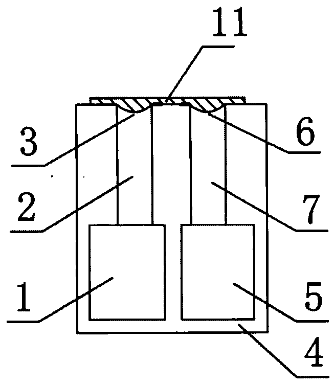
[0039] The external centralized controller communicates and supplies power to the electronically excited detonator, and converts it into a communication signal and a supply voltage through the input circuit, and charges the energy storage capacitor. The switch sends an open signal, and the discharge switch outputs the capacitive energy through the circuit board to the side of the circuit board. Input and output electrons excite the conductive material ignition device Figure 6 , the first pad electrode 1, the second pad electrode 5 and the conductive material 11 welded to the PCB circuit board are at a 90° right angle; the conductive material 11 is coated between the first discharge area 9 and the second discharge area 10 It is graphene nano conductive coating;

[0040] Depend on Figure 4 and Figure 5 As show...

Embodiment 3

[0042] The device involved in this embodiment is carried out according to embodiment 1, and the specific operation is carried out according to the following steps:

[0043] The external centralized controller communicates and supplies power to the electronically excited detonator, and converts it into a communication signal and a supply voltage through the input circuit, and charges the energy storage capacitor. The switch sends an open signal, and the discharge switch outputs the capacitive energy through the circuit board to the side of the circuit board. Input and output electrons excite the conductive material ignition device Figure 6 , the first pad electrode 1, the second pad electrode 5 and the conductive material 11 welded to the PCB circuit board are at a 90° right angle; the conductive material 11 is coated between the first discharge area 9 and the second discharge area 10 Conductive coating for laser printer toner + nickel powder + nano graphite powder;

[0044] ...


PUM


Abstract

The invention relates to a conductive material igniting method by inputting and outputting a electronic excitation from a side of a circuit board. The device involved in the method is composed of a PCB printed circuit board, a first bonding pad electrode, a first circuit, a first metallization half hole, an insulation region, a second bonding pad electrode, a second metallization half hole, a second circuit, a discharge region, a first discharge end, a second discharge end and a conductive material. According to the method, an external integrated controller is used for carrying out communication power supply on the electronic excitation detonator. The power is converted into a communication signal and a supply voltage through an input circuit and an energy storage capacitor is charged. After the communication of the integrated controller and the electronic excitation detonator is finished, a detonation command is sent out, a single-chip microcomputer sends an opening signal to the a discharging switch. The discharge switch outputs the capacitance energy to the side surface of the input/output electronic excitation conductive material ignition device of the circuit board through thecircuit board. A conductive material is coated on the first discharge end, the second discharge end and the discharge region, so that the electric conduction material can generate energy capable of generating fast electronic movement and the flame can be emitted. The flame ignites the basic explosive and detonates detonator, and replaces an ignition bridge wire and a firing powder head in the electric detonator and the electronic detonator.

Description

technical field [0001] The invention relates to a method for firing conductive material by inputting and outputting electrons on the side of a circuit board replacing traditional electric detonators and electronic detonator bridge wire firing powder heads. Background technique [0002] The ignition of the traditional electric heating bridge wire is the ignition device of the electric detonator and the electronic detonator, and the ignition powder is the ignition device for igniting the detonator. The performance of the ignition device directly affects the performance of the blasting system. At present, the more commonly used ignition devices include bridge wire pyrotechnics, film bridge pyrotechnics, semiconductor bridge pyrotechnics, metal film bridge pyrotechnics, explosive film bridge pyrotechnics, etc. The mode of action of bridge wire electric fire heating and pyrotechnic agent is mainly the mechanism of heat conduction. The structure of the bridge wire is simple, and...

Claims


Application Information

Patent Timeline
IPC IPC(8): F42C19/12
CPCF42C19/12
Inventor 赵伽文赵继鹏
Owner 赵伽文
Why Eureka
Try Eureka