Antenna radiation pattern measuring system based on unmanned aerial vehicle platform

An antenna radiation and measurement system technology, applied to the antenna radiation pattern and other directions, can solve the problems affecting the antenna radiation characteristics, difficult to evaluate accurately, and difficult to implement research, so as to speed up the measurement, improve the safety of the measurement, and improve the measurement The effect of efficiency

Inactive Publication Date: 2019-02-01
浙江奇赛其科技有限责任公司 +1
View PDF5 Cites 11 Cited by
  • Summary
  • Abstract
  • Description
  • Claims
  • Application Information

AI Technical Summary

Problems solved by technology

Second, for large directional antennas, it is difficult to evaluate whether the antenna achieves the desired beam coverage effect without the measurement means of the antenna pattern, whether in the development process or in the use process
Let’s take the research of large-scale array antennas as an example. Without the measurement data of the antenna pattern, it is impossible to evaluate the beam quality of the antenna after the array (maximum beam pointing, 3dB beam width, side lobe level, etc.), and relevant research is difficult to implement.
Third, the installation environment of a large antenna directly affects the radiation characteristics of the antenna. Without the measurement methods of the antenna pattern and gain, it is difficult to accurately evaluate the impact of the installation environment on the performance of the antenna, and further optimize the antenna installation on this basis to improve the antenna. Performance, etc., not repeat them one by one
[0006] To sum up, on the one hand, due to the constraints of the objective laws of the working frequency band, it is difficult to measure the gain and pattern of large antennas using conventional antenna measurement methods
On the other hand, due to the lack of effective measurement of large-scale antenna gain and pattern, the development of large-scale antennas in my country is restricted, including the research, development, production, acceptance and use of antennas.

Method used


Image

  • Antenna radiation pattern measuring system based on unmanned aerial vehicle platform
  • Antenna radiation pattern measuring system based on unmanned aerial vehicle platform
  • Antenna radiation pattern measuring system based on unmanned aerial vehicle platform

Examples


Embodiment Construction

[0023] The specific implementation manners of the present invention will be further described in detail below in conjunction with the accompanying drawings and embodiments. The following examples are used to illustrate the present invention, but are not intended to limit the scope of the present invention.

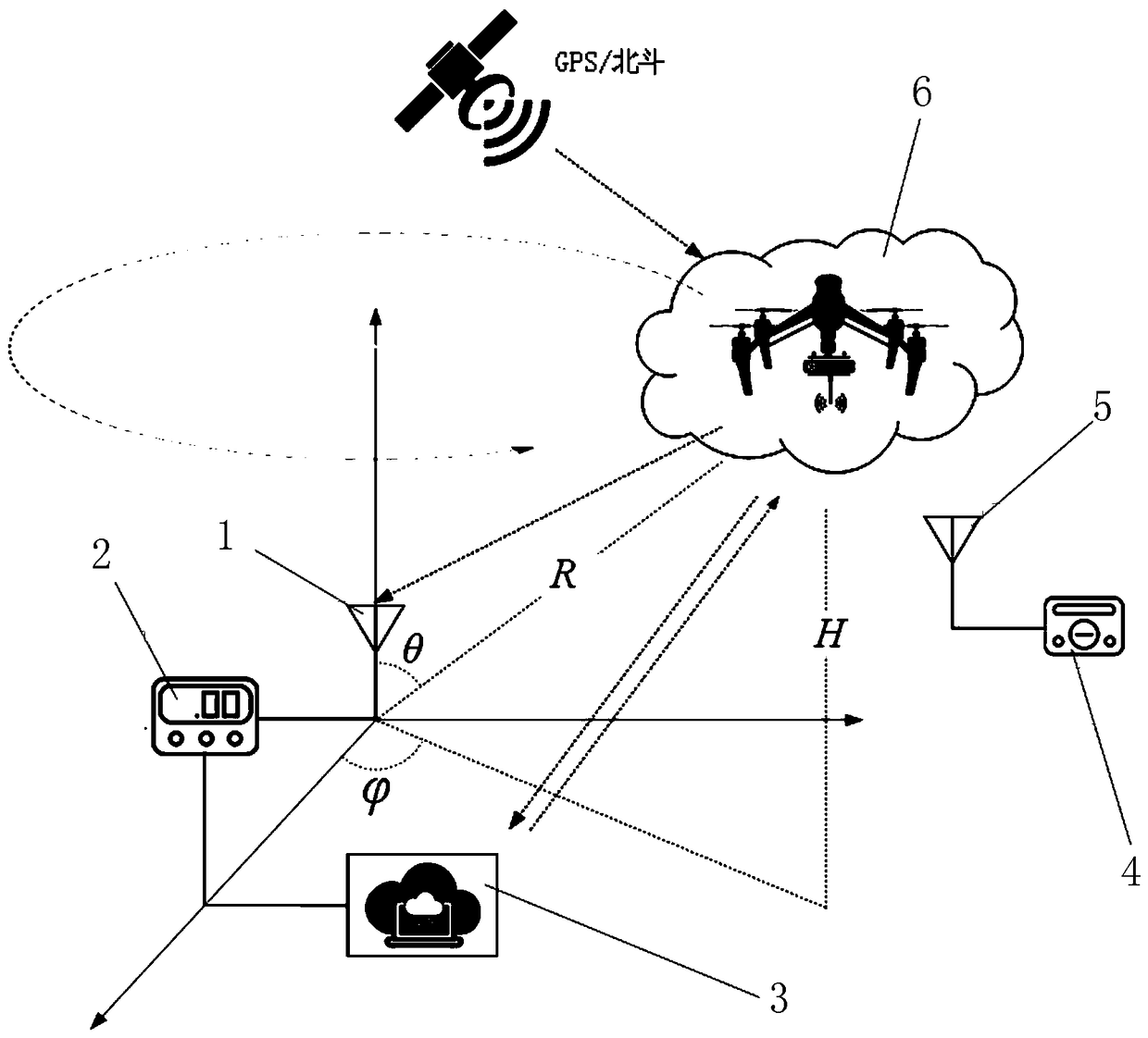
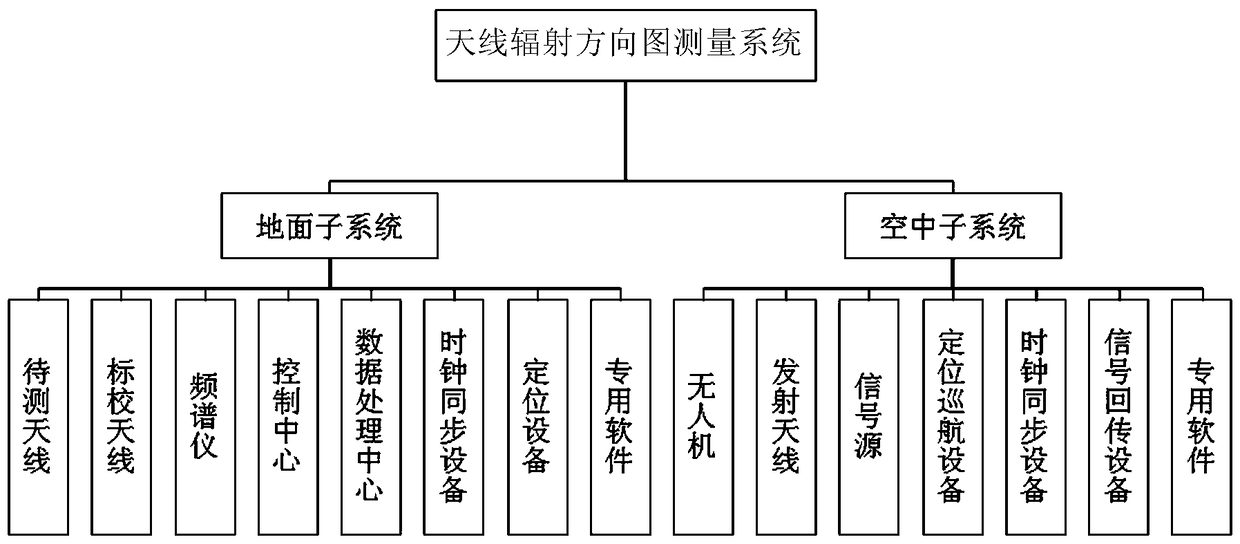
[0024] like figure 1 As shown, the antenna radiation pattern measurement system based on the UAV platform of the present invention includes a ground subsystem and an air subsystem, wherein the ground subsystem consists of an antenna to be tested (installed on a communication site), a calibration antenna, and a spectrum analyzer 2 , control and processing center 3 and other parts, the air subsystem is composed of UAV 6, transmitting antenna 5, signal source 4, positioning cruise equipment 7, signal return equipment and other parts, positioning cruise equipment 7 uses GPS or Beidou satellite In order to realize positioning, distance measurement, height measurement and time ...


PUM


Abstract

The invention discloses large antenna radiation pattern measuring system based on a unmanned aerial vehicle platform, comprising a ground subsystem and an air subsystem. The ground subsystem is composed of a to-be-tested antenna (arranged on the field), a calibration antenna, a spectrometer, a controlling and data processing center and the like. The air subsystem is composed of an unmanned aerialvehicle, a transmitting antenna, a signal source, a positioning cruising device, a data return and the like. In addition, the unmanned aerial vehicle and the ground control center further comprise satellite positioning equipment to realize positioning, ranging, high measurement and time synchronization functions. According to the large antenna radiation pattern measuring system based on the unmanned aerial vehicle platform, influence of the actual installation environment of the large antenna can be taken into account, three-dimensional radiation parameters of the antenna, the far-field radiation pattern and gain of the large antenna are measured in site by the uav / unmanned aerial vehicle.

Description

technical field [0001] The invention relates to the field of wireless communication, and relates to an antenna radiation pattern measurement system, in particular to an antenna radiation pattern measurement system based on an unmanned aerial vehicle flight platform. Background technique [0002] As the main means of communication now, wireless communication is widely used in various fields. Antennas, especially large-scale antennas, have the advantages of long transmission distance and strong invulnerability. Even in today's abundant communication means, they are still a very important and irreplaceable means of communication. [0003] However, it is necessary to point out that the measurement technology of large-scale antennas, especially the measurement technology of radiation parameters (pattern and gain) of large-scale antennas is seriously lagging behind. At present, relevant research is almost blank, which seriously restricts the research, development and production of...

Claims


Application Information

Patent Timeline
Patent Type & Authority Applications(China)
IPC IPC(8): G01R29/10
CPCG01R29/10
Inventor 李建峰陶涛
Owner 浙江奇赛其科技有限责任公司
Why Eureka
Try Eureka