Dry contact flat plate heat pipe floor radiation heating method and heating system

A flat plate heat pipe and radiant heating technology, applied in hot water central heating systems, heating systems, indirect heat exchangers, etc., can solve the problems of low stability and reliability, poor heat exchange capacity, etc. The effect of increasing the speed and reducing the flow resistance

Pending Publication Date: 2019-02-05
赵耀华
View PDF4 Cites 3 Cited by
  • Summary
  • Abstract
  • Description
  • Claims
  • Application Information

AI Technical Summary

Problems solved by technology

[0004] In order to solve the problems of poor heat transfer capacity, low stability and reliability in the prior art, the technical solution of the present invention is as follows:

Method used


Image

  • Dry contact flat plate heat pipe floor radiation heating method and heating system
  • Dry contact flat plate heat pipe floor radiation heating method and heating system
  • Dry contact flat plate heat pipe floor radiation heating method and heating system

Examples


Embodiment 1

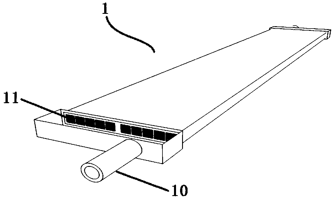
[0040] Such as figure 1 , the present embodiment is for heating a small-area space, and the flat water tank pipe 1 is preferably used as the hot water supply pipe. The capillary micro-groove improves the heat exchange efficiency of the water supply pipe.

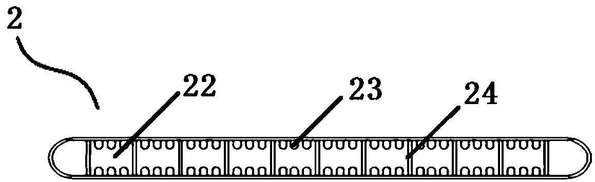
[0041] Such as figure 2 , 4 , 5, the heating system of the present invention adopts the micro heat pipe array 2 as the radiating pipe, and the micro heat pipe array 2 is a plate structure with a plurality of independent micro through holes 22 arranged side by side through welding or stamping or extrusion of metal materials body, the micro-toothed fins 23 are provided on the side walls of the micro-through holes 22, a large number of capillary micro-groove structures are provided on the micro-through-hole wall 24, and the two ends of the micro-heat pipe array 2 are sealed and packaged; the present invention fills the micro-heat pipe array 2 In the working environment of the present invention, a condensing agent capable of...

Embodiment 2

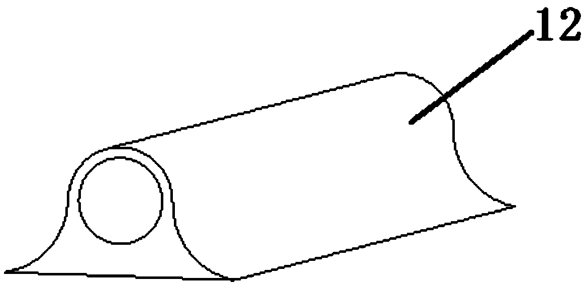
[0046] This embodiment provides heating for a large area of ​​space, such as image 3 As shown, the airfoil pipe 12 is used as the hot water supply pipe. The pipe of the airfoil pipe 12 is thick, which reduces the flow resistance of the working fluid and improves the circulation efficiency of the working fluid. The special shape of the airfoil pipe 12 can be well integrated with micro The heat pipe array is bonded, and compared with the traditional round pipe, the heat exchange area is increased and the heat exchange efficiency is improved. The heat dissipation section of the micro heat pipe array 2 forms an included angle of 4.5° with the horizontal ground, and other structures are similar to those in Embodiment 1.

Embodiment 3

[0048] Compared with Embodiment 1, this embodiment has two pads 6 of the same height, the micro heat pipe array 2 is placed horizontally, and microchannels with capillary structure are arranged on the wall surface, and the reflux circulation of the condensing agent is assisted by its capillary adsorption force. Other structures and implementations Example 1 is similar.


PUM


Abstract

The invention discloses a floor radiation heating system based on micro heat pipe arrays. The heating system comprises a hot water supply pipe, and multiple micro heat pipe arrays; the hot water supply pipe is a flat water tank pipe or a wing pipe with the lower surface as a plane; the micro heat pipe arrays are plate structural bodies formed by welding or punching or extruding metal materials andwith multiple parallel independent micro through holes; micro tooth fins are arranged on the side walls of the micro through holes; a lot of capillary groove structures are arranged on the inner walls of the micro through holes; two ends of the micro heat pipe arrays are tightly sealed; the micro heat pipe arrays are filled with condensing agents; when the micro heat pipe arrays are inclined in the length directions, condensing agent covering sections are evaporation sections, and the rest sections are heat dissipating sections; and the lower surface of the hot water supply pipe is bonded with the evaporation sections of the micro heat pipe arrays through heat conducting silica gel. The heating system changes a traditional base plate heating mode, and is uniform in floor heating temperature distribution, high in heat supply efficiency and low in energy consumption; and the whole set of system pipelines is simple and convenient to maintain.

Description

technical field [0001] The invention relates to a dry contact type flat heat pipe floor radiant heating method and a floor radiant heating system based on a micro heat pipe array, belonging to the field of heating and heating. Background technique [0002] The traditional indoor heating method is mainly radiator heating, that is, radiators such as radiators are arranged on the inner wall of the building, and radiators such as radiators are usually hung on the indoor wall. The indoor space is larger. And because the radiator is suspended on the wall, it is difficult for the heat dissipated by the radiator to be transferred downward, resulting in uneven temperature distribution in the space. Since radiators such as radiators are usually hung on the wall, the heat dissipation area is usually the peripheral area of ​​the room, and a large part of the heat emitted by the radiator is transferred to the outside through the walls, doors and windows, resulting in high water supply t...

Claims


Application Information

Patent Timeline
Patent Type & Authority Applications(China)
IPC IPC(8): F24D3/14F28D15/04
CPCF24D3/14F28D15/04F28D2015/0225
Inventor 赵耀华靖赫然全贞花董瑞雪
Owner 赵耀华
Why Eureka
Try Eureka