Receiver of wireless charging system, control method of receiver, electrical terminal, transmitter of wireless charging system and wireless charging system

A wireless charging and receiving end technology, applied in charging stations, battery circuit devices, high-efficiency power electronic conversion, etc., can solve problems such as the reduction of output power of wireless charging systems

Active Publication Date: 2019-02-12
HUAWEI TECH CO LTD
View PDF3 Cites 19 Cited by
  • Summary
  • Abstract
  • Description
  • Claims
  • Application Information

AI Technical Summary

Problems solved by technology

However, in the prior art, when the controllable switching tube of the rectifier realizes zero-voltage switching, the output power of the wireless charging system will be significantly reduced

Method used


Image

  • Receiver of wireless charging system, control method of receiver, electrical terminal, transmitter of wireless charging system and wireless charging system
  • Receiver of wireless charging system, control method of receiver, electrical terminal, transmitter of wireless charging system and wireless charging system
  • Receiver of wireless charging system, control method of receiver, electrical terminal, transmitter of wireless charging system and wireless charging system

Examples


Embodiment 1

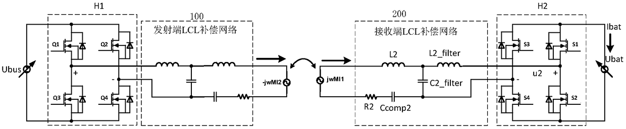
[0089] see figure 2 , which is a schematic diagram of a receiving end of a wireless charging system provided in an embodiment of the present application.

[0090] The transmitting end and the receiving end of the wireless charging system generally include a compensation network, and the compensation network is a network formed by equivalently combining a compensation circuit and a coil. Generally, in order to achieve structural symmetry, the transmitting end and the receiving end can use the same type of compensation network. figure 2 The transmitter compensation network is not shown in the figure, only the receiver compensation network is shown.

[0091] figure 1 It has already been introduced that the receiving end includes the receiving coil, the receiving end compensation circuit and the rectifier H2, and details will not be repeated here. The improvement points of the embodiments of the present application are mainly introduced below. The receiving end of wireless c...

Embodiment 2

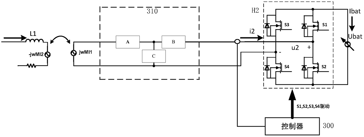
[0151] see Figure 7 , which is a schematic diagram of another receiving end provided by the embodiment of the present application.

[0152] Parts of the receiving end provided in this embodiment that are the same as those in Embodiment 1 will not be repeated here.

[0153] In this embodiment, the controller 300 is specifically used to control the phase difference between the first bridge arm and the second bridge arm of the rectifier H2 to be the target phase difference α; α is used to adjust the resistance of the equivalent impedance of the rectifier, in this embodiment The controller 300 receives the target phase difference α. And control the phase shift angle β of the arm voltage of the rectifier H2 and the fundamental component of the input current to be π−α+σ; σ is the first preset value; and σ is the first preset value set inside the controller 300 . The controller 300 can preset σ as a small positive value, for example, set σ as a value between. σ is used to adjus...

Embodiment 3

[0195] see Figure 12 , which is a schematic diagram of a receiving end of another wireless charging system provided by an embodiment of the present application.

[0196] Image 6, Figure 7 and Figure 12 Both are introduced by taking the integration of the sub-inductance branch and the inductance compensation module as an example.

[0197] In this embodiment, the controller 300

[0198] Specifically, the phase difference between the first bridge arm and the second bridge arm of the rectifier H2 can be controlled to be a preset phase difference α; the preset phase difference is used to adjust the resistance of the equivalent impedance of the rectifier. In this embodiment, α is the control σ is the value received by the controller 300 from the outside, and the controller 300 also controls the phase shift angle β of the bridge arm voltage of the rectifier H2 and the fundamental wave component of the input current to be π-α+σ; σ is the target value; the target value σ is used...


PUM


Abstract

The invention discloses a receiver of a wireless charging system, a control method of the receiver, an electrical terminal, a transmitter of the wireless charging system and a wireless charging system. The receiver includes a receiving coil, a receiver compensation circuit, a rectifier and a controller; the controller adjusts a phase difference between first and second bridge arms of the rectifierand adjusts a phase shift angle between bridge arm voltage of the rectifier and input current fundamentals component of the rectifier, thereby allowing zero-voltage on and off of a controllable switch of the rectifier. The magnitude of the fundamental component of the bridge arm voltage is adjusted by adjusting the phase difference between the two bridge arms of the rectifier, thereby adjusting areal part of equivalent impedance of the rectifier. The equivalent impedance of the rectifier includes the real part and a virtual part; the real part refers to resistance; the virtual part refers toreactance. When the virtual part of the equivalent impedance of the rectifier is very small, the equivalent impedance of the rectifier is considered as pure-resistive impedance, and the controllableswitch tube gains ZVS (zero-voltage switching) effect. An inductance compensation module helps weaken the capacitive portion of the equivalent impedance, thereby lowering reactive power of the wireless charging system and improving system efficiency of the wireless charging system.

Description

technical field [0001] The present invention relates to the technical field of power electronics, in particular to a receiving end, a method, a power consumption terminal, a transmitting end and a system of a wireless charging system. Background technique [0002] With the aggravation of energy shortage and environmental pollution in modern society, electric vehicles, as new energy vehicles, have attracted widespread attention from all walks of life once they were launched. However, most of the existing electric vehicles are limited by the battery capacity, and the mileage is short. At the same time, the battery charging time of electric vehicles is long, and the corresponding charging station resources are poor, which has become a bottleneck restricting the application and popularization of electric vehicles. [0003] Battery charging methods for electric vehicles generally include: contact charging and wireless charging. Among them, the contact charging uses the metal con...

Claims


Application Information

Patent Timeline
Patent Type & Authority Applications(China)
IPC IPC(8): H02J7/02H02M7/219B60L53/22
CPCH02J7/025H02M7/219H02M1/0058H02J3/18H02J7/02H02M7/5387H02J50/12Y02B70/10Y02E40/30Y02T10/70Y02T10/7072Y02T90/14
Inventor 毛云鹤刘彦丁
Owner HUAWEI TECH CO LTD
Why Eureka
Try Eureka