Permanent magnet synchronous motor control method and control system based on pulsating high-frequency voltage injection

A technology of permanent magnet synchronous motor and control method, which is applied in the direction of motor generator control, electronic commutation motor control, control system, etc., and can solve the problems of slow dynamic response, unfavorable promotion and use, and lag of rotor position and speed

Inactive Publication Date: 2019-02-12
RES INST OF PHYSICAL & CHEM ENG OF NUCLEAR IND
View PDF8 Cites 7 Cited by
  • Summary
  • Abstract
  • Description
  • Claims
  • Application Information

AI Technical Summary

Problems solved by technology

[0003] There are several algorithms commonly used for position sensors, such as pulse vibration high-frequency voltage injection, sliding mode observer, and back EMF integrator. Among them, pulse vibration high-frequency voltage injection is suitable for the control operation of the motor at zero speed and low speed.

Method used


Image

  • Permanent magnet synchronous motor control method and control system based on pulsating high-frequency voltage injection
  • Permanent magnet synchronous motor control method and control system based on pulsating high-frequency voltage injection
  • Permanent magnet synchronous motor control method and control system based on pulsating high-frequency voltage injection

Examples


Embodiment 1

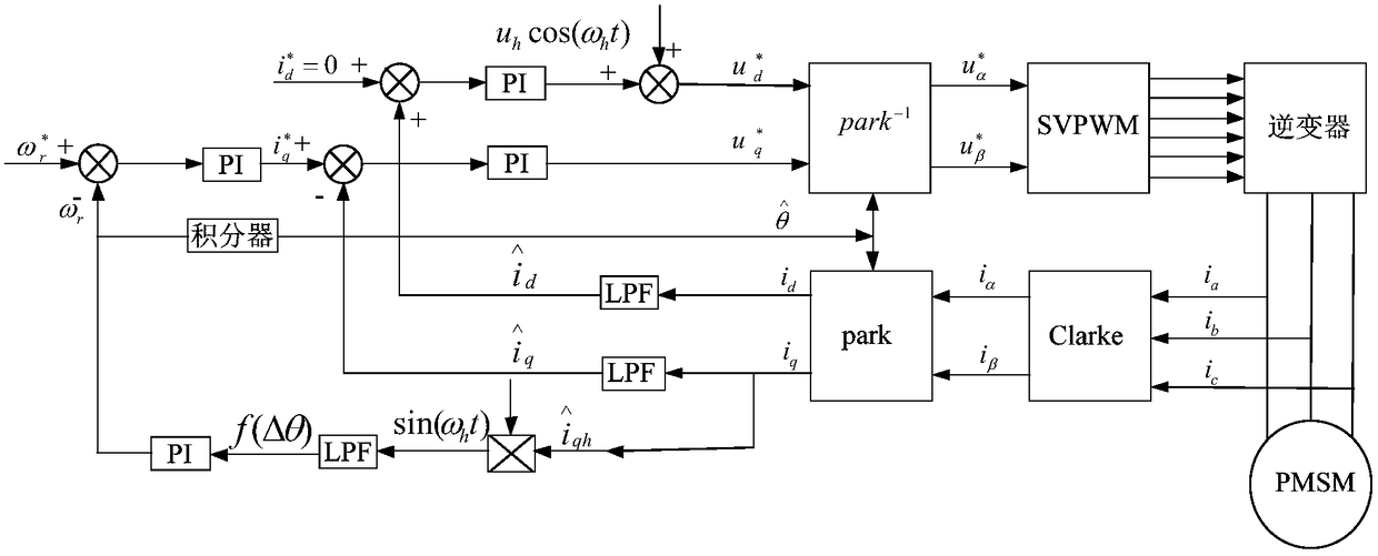
[0037] As shown in the figure, the surface mount permanent magnet synchronous motor adopts i d= 0 control method, the rotor position angle is detected by the pulse vibration high-frequency voltage injection method, which specifically includes the following steps,

[0038] 1) Inject a high-frequency voltage signal into the direct axis of the estimated two-phase rotating coordinate system, and generate a high-frequency current under the excitation of the high-frequency voltage signal,

[0039] 2) The high-frequency current is transformed through coordinates and combined with the modulating signal sin(ω h t) is multiplied to obtain the high-frequency current component ω h is the phase of the high-frequency voltage signal,

[0040] 3) High-frequency current component The speed ω of the motor is obtained by low-pass filtering (LPF) and PI regulator r , where the control is zero, so that the error Δθ between the estimated value of the rotor position and the actual value gra...

Embodiment 2

[0078] Among them, the detected rotor angle is also included in the calculation of the real-time speed ω of the motor r To complete the step of speed adjustment, the described speed adjustment step is, the real-time speed ω r with set speed The deviation value is obtained by the speed PI regulator i q Current reference value The current i of the motor is calculated by the Clarke and Park transformation q i d , current i q i d After the high-frequency current components are filtered out by a low-pass filter, they are respectively compared with the reference value 0 value for comparison, the generated deviation value is then passed through the current PI regulator to obtain the given value of the voltage and The two are then subjected to park inverse transformation to generate a given voltage value and and It is the control signal of the three-phase inverter SVPWM, and the purpose of adjusting the motor speed is achieved by controlling the output of the invert...

Embodiment 3

[0081] The modulation signal is sin(ω h t), for in are the high-frequency impedance phase angles of the d and q axes, respectively, Z dh ,Z qh are the high-frequency impedances of the d and q axes respectively, and j is the imaginary unit, where,

[0082] Z dh =R s +jω h L d ,Z qh =R s +jω h L q ,

[0083] In order to ensure the stability of the rotor position estimation system, the modulation signal is improved, and the stability of the rotor position estimation system is not restricted by the motor parameters and the frequency of the injected signal. high frequency current component The extraction of is usually obtained by filtering the iq current after the coordinate transformation by using a band-pass filter. In the application process of the present invention, the band-pass filter is directly omitted, and the iq current after the coordinate transformation is directly compared with the modulation signal multiplied. Without using a band-pass filter, the...


PUM


Abstract

The invention discloses a permanent magnet synchronous motor control method and control system based on pulsating high-frequency voltage injection. The permanent magnet synchronous motor control method based on pulsating high-frequency voltage injection does not adopt a band-pass filter, computation burden can be greatly decreased, computational efficiency is improved, dynamic response of a systemis improved, program complexity is reduced, and high-frequency component containing rotor position information can be remained as far as possible when the band-pass filter is not used. A high-frequency impedance angle is introduced, modulating signals are improved, the stability of a rotor position estimation system cannot be restricted by motor parameters and injection signal frequency, and thestability of the rotor position estimation system is ensured.

Description

technical field [0001] The invention belongs to the technical field of motor control, and in particular relates to a permanent magnet synchronous motor control method and control system based on pulse vibration high-frequency voltage injection. Background technique [0002] Permanent magnet synchronous motors are widely used in the field of industrial control due to their advantages such as efficient energy utilization and excellent mechanical properties. Permanent magnet synchronous motors usually adopt the vector control method, which needs to detect the rotor position and angle at all times for calculation control. The rotor position and angle are generally obtained by mechanical position sensors, but the existence of mechanical sensors not only increases the size and cost of the motor, but also reduces the system reliability. [0003] There are several algorithms commonly used for position sensors, such as pulse vibration high-frequency voltage injection, sliding mode o...

Claims


Application Information

Patent Timeline
IPC IPC(8): H02P21/18H02P21/24H02P25/022
CPCH02P21/18H02P21/24H02P25/022H02P25/024H02P2203/11H02P2207/05
Inventor 魏振姚广赵楠任祥正张楠
Owner RES INST OF PHYSICAL & CHEM ENG OF NUCLEAR IND
Why Eureka
Try Eureka