PLC (Programmable Logic Controller) controlled denitration device

A technology of denitration and main body, applied in the field of denitration, can solve the problems of uneven thickness of catalyst, influence reaction efficiency, insufficient reaction of nitrogen oxides, etc., and achieve the effect of improving reaction effect, improving reaction efficiency and uniform catalyst layer.

Inactive Publication Date: 2019-02-15
西安安迈工业自动化技术有限公司
View PDF0 Cites 2 Cited by
  • Summary
  • Abstract
  • Description
  • Claims
  • Application Information

AI Technical Summary

Problems solved by technology

[0003] At present, the thickness of the catalyst on the catalyst plate in the denitration device is uneven, and the flue gas will pass through at a thinner position. The nitrogen oxides in the flue gas cannot fully react, which affects the reaction efficiency. Therefore, it is necessary to improve it.

Method used


Image

  • PLC (Programmable Logic Controller) controlled denitration device
  • PLC (Programmable Logic Controller) controlled denitration device

Examples


Embodiment approach

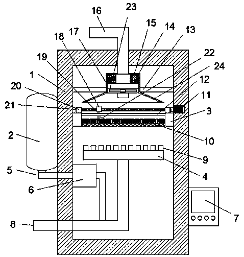
[0023] As a preferred embodiment of the present invention, a PLC controller 7 is fixed on the outside of the device main body 1, and the PLC controller 7 is electrically connected to the evaporator 6, the motor 11, the exhaust fan 23 and the electric heating rod 15 respectively.

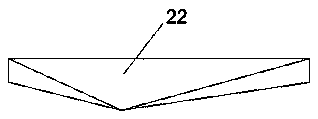
[0024] As a preferred embodiment of the present invention, the heat conduction block 14 is a hollow cylindrical structure, and the heat conduction block 14 is made of copper or aluminum.

[0025] As a preferred embodiment of the present invention, the catalyst plate 3 is provided with a limiting rod 12 , and the connecting rod 19 passes through the limiting rod 12 .

[0026] As a preferred embodiment of the present invention, the motor 11 is a forward and reverse motor.

[0027] When the denitrification device is in use, a guide plate is arranged at the end of the smoke inlet pipe, and a plurality of smoke outlets are arranged on the upper surface of the guide plate, so that the mixed gas of flue gas...


PUM


Abstract

The invention discloses a PLC (Programmable Logic Controller) controlled denitration device which comprises a device main body, an ammonia gas tank and a catalyst plate, wherein a smoke inlet tube isarranged on one side of the device main body; one end of the smoke inlet tube is connected with the bottom of a guide plate inside the device main body; and a plurality of smoke outlets are formed inthe upper surface of the guide plate. When the denitration device is used, the guide plate is arranged at an end part of the smoke inlet tube, a plurality of the smoke outlets are formed in the uppersurface of the guide plate, a mixed gas of smoke and ammonia gases can be uniform, the mixed gas can uniformly penetrate through a catalyst layer on a filtering plate, and then the reaction effect canbe improved; a rotating rod is arranged on the catalyst plate, one end of the rotating rod is connected with a motor, the rotating rod is sleeved by a sleeve ring, the sleeve ring is connected with apush plate through a connecting rod, the push plate is pushed on the catalyst layer through the rotating rod, the catalyst layer is uniform, the smoke can uniformly penetrate through the catalyst layer, nitric oxides in the smoke can be sufficiently reacted, and the reaction efficiency can be improved.

Description

technical field [0001] The invention relates to the technical field of denitrification, in particular to a PLC-controlled denitrification device. Background technique [0002] In industrial flue gas, it usually means a large amount of nitrogen oxides, and nitrogen oxides is one of the main air pollutants, and it is also the main cause of acid rain, photochemical smog, high ground ozone concentration and greenhouse effect, which seriously damages the human health and living environment. Therefore, active research and development of flue gas denitrification technology has important environmental, economic and social benefits. [0003] At present, the thickness of the catalyst on the catalyst plate in the denitrification device is uneven, and the flue gas will pass through at a thinner position. The nitrogen oxides in the flue gas cannot fully react, which affects the reaction efficiency. Therefore, it is necessary to improve it. Contents of the invention [0004] In view o...

Claims


Application Information

Patent Timeline
Patent Type & Authority Applications(China)
IPC IPC(8): B01D53/90B01D53/56G05B19/05
CPCB01D53/90B01D53/8631B01D2251/2062B01D2258/0283G05B19/05
Inventor 王文骏
Owner 西安安迈工业自动化技术有限公司
Why Eureka
Try Eureka