Method for directly manufacturing cold cathode flat plate X-ray detector on scintillator and structure thereof

A cold cathode and scintillator technology, applied in the direction of electric solid devices, semiconductor devices, radiation intensity measurement, etc., can solve the problems of pixel point influence, easy pollution, scattering, etc., increase the number and energy of electrons, improve detection sensitivity, increase Effective voltage effect

Active Publication Date: 2019-02-15
SUN YAT SEN UNIV
View PDF5 Cites 7 Cited by
  • Summary
  • Abstract
  • Description
  • Claims
  • Application Information

AI Technical Summary

Problems solved by technology

The method of packaging the scintillator and the photodetector device array into the box disclosed in this prior art uses a colloidal film layer or applies a pressure vacuum to the box during the packaging process, which is easy to contaminate and damage the photodetector device, reducing the performance of the detector.
[0004] In addition, by introducing a protective layer between the scintillator and the photodetector array, the damage to the device can be reduced by pack

Method used


Image

  • Method for directly manufacturing cold cathode flat plate X-ray detector on scintillator and structure thereof
  • Method for directly manufacturing cold cathode flat plate X-ray detector on scintillator and structure thereof
  • Method for directly manufacturing cold cathode flat plate X-ray detector on scintillator and structure thereof

Examples


Embodiment 1

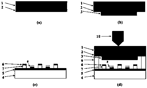
[0037] Please also see figure 1 (a)~ figure 1(d), a method for directly making a cold cathode flat-panel X-ray detector on a scintillator according to the present embodiment comprises the following process steps:

[0038] Step S1: Prepare a light-transmitting anode electrode 2 on one side of the scintillator 1, such as figure 1 (a) shown.

[0039] The scintillator 1 adopts materials capable of converting X-rays into visible light, and the materials include CsI, CaWO 4 , YTaO 4 、Gd 2 o 2 S. Bi 4 Ge 3 o 12 or Lu 2 SiO 5 . The anode electrode 2 formed by the ITO electrode was plated on one side of the scintillator by magnetron sputtering technology, the power during coating was 1.2KW, the coating rate was 14nm / min, and the thickness of the anode electrode 2 was 500nm. The anode electrode 2 is transparent to the light emitted by the scintillator, and is connected with a lead wire connected to the first external voltage source, and a voltage is applied to the anode elec...

Embodiment 2

[0053] This embodiment uses specific examples to describe in detail the detailed process of directly fabricating a cold-cathode flat-panel X-ray detector on a scintillator in the present invention.

[0054] (1) First, prepare a CsI scintillator with an area of ​​12.5cm×9.5cm and a thickness of 1mm. Then use the magnetron sputtering technology to plate the ITO electrode on the surface of the scintillator as an anode electrode. The thickness of the ITO electrode is 500nm, the coating power is 1.2KW, and the coating rate is 14nm / min. (2) Then, a ZnS photoconductor was plated on the middle area of ​​the ITO electrode surface by electron beam evaporation technology, with a thickness of 4 μm, an area of ​​4.5 cm×8 cm, and a coating rate of 1 nm / s. (3) Next, an addressable cold cathode electron source is prepared on a glass substrate, the thickness of the glass substrate is 3 mm, and the area of ​​the cold cathode electron source is 4.5 cm×8 cm. The cathode electrode strips and grid...

Embodiment 3

[0057] The difference between this example and Example 2 lies in the process of preparing the ZnS photoconductor on the anode electrode of the scintillator by using screen printing technology, and other steps are consistent with Example 2. The specific preparation process is as follows: first, the potassium silicate solution and ZnS powder are stirred evenly to form a ZnS melt; then the ZnS melt is prepared on the electrode on the scintillator by screen printing technology, with a thickness of 20 μm and an area of ​​4.5cm× 8cm; Finally, the above-prepared samples were dried on a hot plate. The preparation methods of other structures in this example are as described in Example 2.


PUM

PropertyMeasurementUnit
Heightaaaaaaaaaa
Thicknessaaaaaaaaaa

Abstract

The invention discloses a method for directly manufacturing a cold cathode flat plate X-ray detector on a scintillator. The method comprises the following process steps of (1) preparing an anode electrode on the scintillator; (2) preparing a photoconductor on the anode electrode; (3) preparing a cold cathode substrate; (4) mutually insulating and fixing one side, which is prepared with the photoconductor, of the scintillator and one side, which is prepared with a cold cathode, of the cold cathode substrate through an isolator; and (5) retaining a vacuum state between the scintillator and the cold cathode substrate. The invention simultaneously discloses the cold cathode flat plate X-ray detector prepared by the abovementioned method. The scintillator in the invention possesses the functionof a substrate support and the function of converting an X-ray into a visible light; photon scattering can be effectively avoided; the problem of integration of the scintillator on the X-ray detectoris solved; and the X-ray imaging function can be implemented by use of an addressable cold cathode electron source.

Description

technical field [0001] The invention relates to a method and structure for directly manufacturing a cold cathode flat-panel X-ray detector on a scintillator, belonging to the field of flat-panel X-ray detectors. Background technique [0002] X-ray imaging is widely used in fields such as medicine, security inspection, non-destructive testing and industrial flaw detection. High-sensitivity flat-panel X-ray detectors are the key to low-dose X-ray imaging. At present, the mainstream flat-panel X-ray detectors use thin-film transistors to read photoelectric signals, but the X-ray detectors using thin-film transistors have complex structures and are prone to breakdown under high voltage, which affects their practical applications. In order to improve the spatial resolution and quantum detection efficiency, researchers began to use a vacuum tube composed of a cold cathode based on the field electron emission principle as a readout device to realize a flat-panel X-ray detector. F...

Claims


Application Information

Patent Timeline
IPC IPC(8): H01L27/146G01T1/20
CPCG01T1/20H01L27/146H01L27/14601
Inventor 陈军张志鹏王凯邓少芝许宁生
Owner SUN YAT SEN UNIV
Why Eureka
Try Eureka