Continuous chloride production device

A production device and technology of chlorinated substances, applied in the field of chlorinated substances production equipment, can solve problems such as difficulty in effectively improving the production of chlorinated substances, further improvement of production efficiency, and inability to realize continuous production process, so as to improve safety and environmental protection, shorten the total production cost, etc. Response time, the effect of improving intrinsic safety performance and environmental performance

Inactive Publication Date: 2019-02-22
申素英
View PDF3 Cites 4 Cited by
  • Summary
  • Abstract
  • Description
  • Claims
  • Application Information

AI Technical Summary

Problems solved by technology

[0003] At present, the production of chlorinated compounds in industry is mainly based on batch tank liquid phase reaction, that is, chlorine gas or hydrogen chloride gas is directly introduced into liquid raw materials or liquid catalysts, and chlorine atoms are introduced into the raw material molecules under certain temperature and catalytic conditions. Chlorination reaction, because the dissolution rate of the gas-liquid two-phase is lower than the reaction rate, it is difficult to effectively improve the production of chlorinated products, and the batch method limits the further improvement of production capacity
Moreover, in the production of chlorinated compounds in the former industry, according to the principle of mass transfer, the reaction rate was increased by increasing the ventilation rate and reaction pressure, which led to problems such as low gas phase utilization, large consumption of liquid caustic soda, low purity of hydrochloric acid, and low safety.
[0004] For example, the Chinese patent with the publication number CN105154136A discloses a production process and equipment for chlorinated paraffin. The dissolution and reaction in the medium are simultaneously decomposed into gas-liquid two-phase dissolution and absorption in the reaction tower, and the catalytic reaction in the reactor is carried out in two steps, reducing the reaction time of chlorinated paraffin from more than 20h to 4-10h, but its disadvantage lies in its It is a batch reaction, the continuous production process cannot be realized, and the production efficiency cannot be further improved
The Chinese patent with the publication number CN105112100B discloses a continuous production process of chlorinated paraffin. The patent adopts a reactor group composed of six reactors. The liquid wax enters continuously from the first reactor. In the reactor, the chlorinated paraffin that meets the requirements is generated in the last reactor and discharged continuously to realize the continuous production of chlorinated paraffin, but its disadvantage is that the mass transfer rate of chlorine gas and liquid wax is not high, and the average reaction If the time exceeds 20 hours, and the direction of the gas-liquid two-phase flow is consistent, the reaction in the second-stage reactor gradually tends to balance, and the consumption of chlorine in the tail gas by the last-stage reaction is limited, and the chlorine content in the tail gas is relatively high
Publication number CN102875357A has announced the process of producing chloroacetic acid in a large-scale chlorination kettle and the chlorination kettle used for its reaction. It adopts "two main and one auxiliary" three reaction kettles to form an intermittent production device, and the liquid phase is added to the main kettle and the secondary kettle at one time. , to react chlorine gas in the main tank, and the tail gas is fed into the secondary tank to continue the reaction. The disadvantage is that the continuous production process cannot be realized and the reaction speed can be effectively improved.

Method used


Image

  • Continuous chloride production device
  • Continuous chloride production device
  • Continuous chloride production device

Examples


Embodiment 1

[0029] Embodiment 1: the production process device of chlorinated paraffin

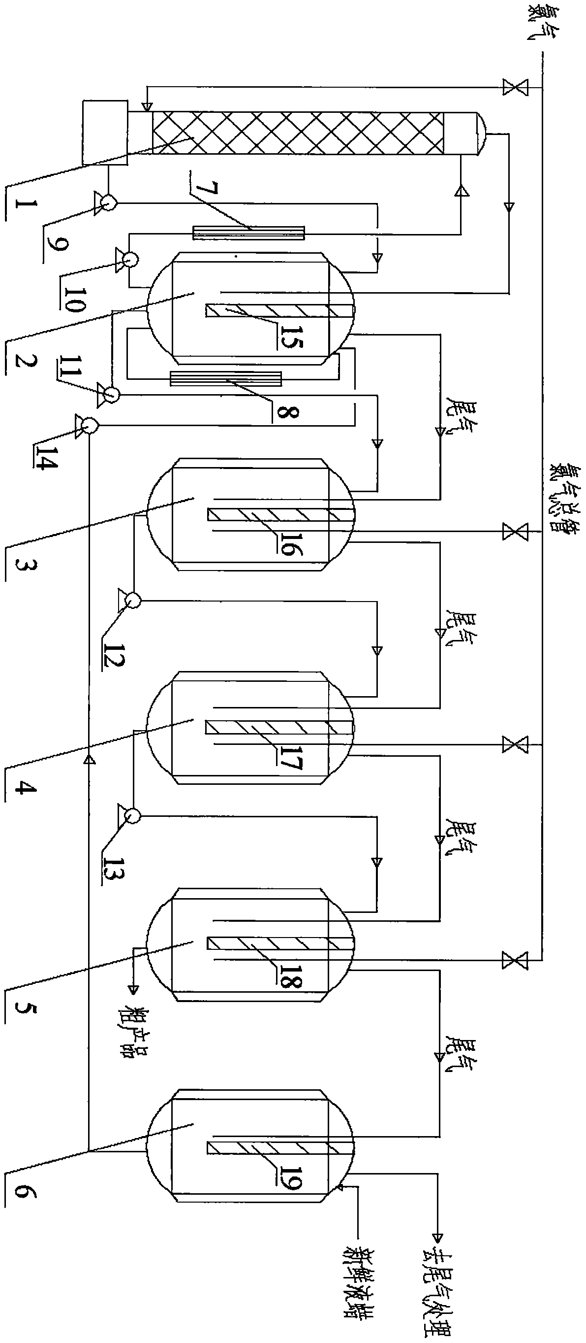
[0030] Such as figure 1 As shown, the production equipment of chlorinated paraffin mainly includes absorption tower 1, reaction kettle 2, refining kettle 3, 4, 5, absorption kettle 6, heat exchanger 7, 8.

[0031] Absorption tower 1 selects glass packed tower for use, and its bottom is provided with chlorine feed inlet and chlorinated paraffin intermediate product (hereinafter referred to as " chlorine wax ") outlet, is respectively used for chlorine feed and saturated chlorine wax discharge after absorbing chlorine, chlorine The wax outlet is connected to the upper feed port of the reaction kettle 2 through the circulation pump 9; the upper part of the absorption tower 1 is provided with a chlorine wax feed inlet and a tail gas outlet, which are respectively connected with the chlorine wax outlet of the lower part of the reaction kettle 2 and the upper part of the reaction kettle. Exhaust gas inlet ...

Embodiment 2

[0038] Embodiment 2: the production process device of chloroacetic acid

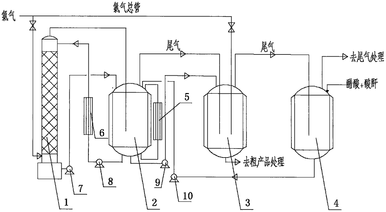
[0039] Such as figure 2 As shown, the production equipment of chloroacetic acid mainly includes an absorption tower 1, a reaction kettle 2, a refining kettle 3, an absorption kettle 4, heat exchangers 5, 6 and a tail gas treatment device.

[0040] The absorption tower 1 is a glass packed tower, the lower part of which is provided with a chlorine gas feed inlet and a chloroacetic acid semi-finished product outlet, which are respectively used for chlorine gas feed and chloroacetic acid semi-finished product discharge after absorbing chlorine gas saturation, and the chloroacetic acid semi-finished product outlet passes through the circulation pump 7 and reacts The upper part of the kettle 2 is connected to the feed port; the upper part of the absorption tower 1 is provided with a chloroacetic acid semi-finished product feed port and a tail gas outlet, which are respectively connected to the chloroacetic ac...

Embodiment 3

[0045] Embodiment 3: the production process device of methyl chloride

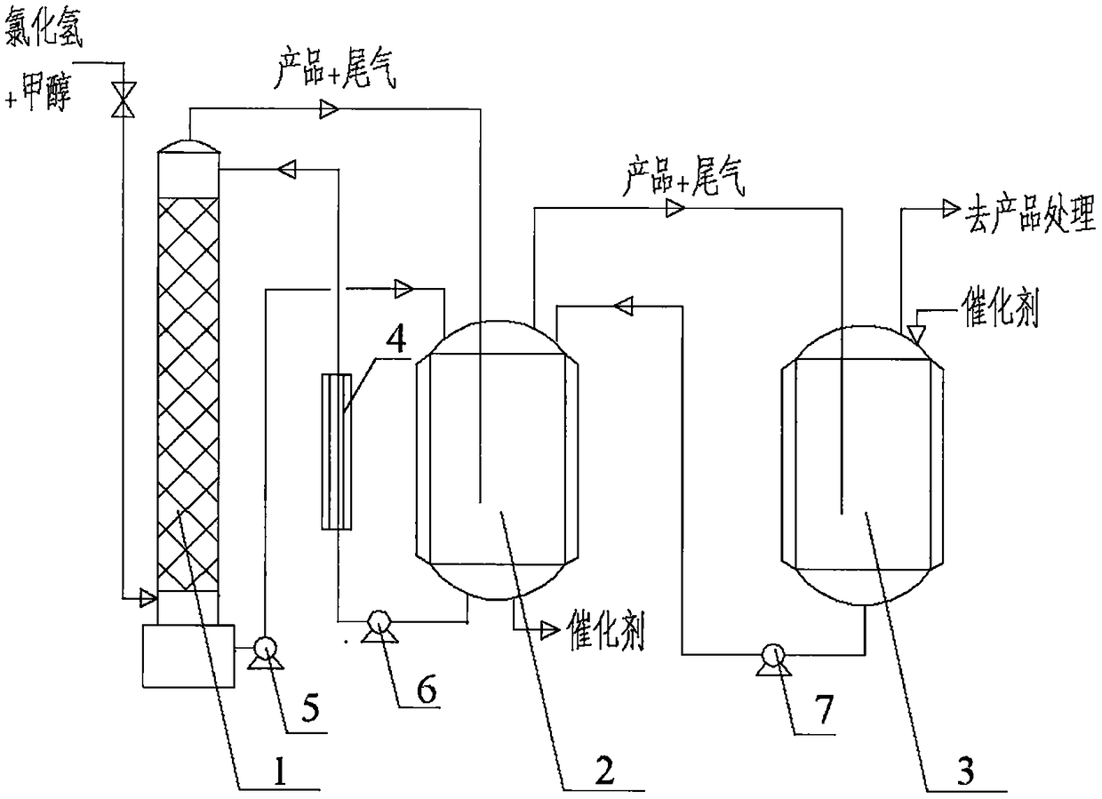
[0046] Such as image 3 As shown, the production equipment of methyl chloride mainly includes an absorption tower 1, a reaction kettle 2, an absorption kettle 3, and a heat exchanger 4.

[0047] The absorption tower 1 is a sieve plate tower, and its lower part is provided with a hydrogen chloride and methanol gas feed port and a catalyst discharge port, which are respectively used for the hydrogen chloride and methanol gas feed and the saturated catalyst discharge after absorbing the gas phase. The pump 5 is connected to the upper feed port of the reactor 2; the upper part of the absorption tower 1 is provided with a catalyst feed port and a product and tail gas outlet, which are respectively connected to the catalyst outlet of the lower part of the reactor 2 and the product and tail gas inlet of the upper part of the reactor 2.

[0048] Reactor 2 is cooled by a jacket, and its lower part is provided with...


PUM


Abstract

The invention discloses continuous chloride production device for continuous production of chlorinated paraffin, chloroacetic acid, methyl chloride and the like. The device comprises all or several ofan absorption tower, a reaction kettle, a refining kettle, an absorption tank, a heat exchanger and an exhaust gas treatment device, wherein the absorption tower is connected with the reaction kettleand the heat exchanger is arranged therebetween; and the reaction kettle is connected the refining kettle and the absorption tank in sequence. Under a stable production state, a gas phase continuously enters the absorption tower and the refining kettle, respectively; a liquid phase is continuously added through the absorption kettle, pre-reacted with the unreacted gas phase, introduced into the reaction kettle, and sequentially introduced into the refining kettle after circularly absorbing the gas phase in the reaction kettle and the absorption tower, and the formed liquid crude product or deactivated catalyst is continuously discharged; the gas formed in the absorption tower sequentially collects the gas in the reaction kettle and the refining tank and then enters the absorption kettle,and after pre-reaction, exhaust gas is removed or collected by a gas product collection device. The device realizes the continuous production of chlorides, improves production efficiency and product yield, and enhances the control performance of reaction.

Description

technical field [0001] The invention belongs to the field of chlorine compound production equipment. In particular, it relates to a new method for continuously and efficiently producing chlorinated compounds by using combined equipment of an absorption tower, a reaction kettle, a refining kettle and an absorption kettle. Background technique [0002] Chlorinated compounds are important chemical raw materials needed in the development of the national economy. For example, chlorinated paraffin has many excellent physical and chemical properties such as low volatility, flame retardancy, good electrical insulation and chemical corrosion resistance, and can be used as a flame retardant polyvinyl chloride Plasticizers, etc., are widely used in the production of plastics, cables, floor materials, hoses, artificial leather and rubber products, and can also be used as additives for paints, coatings and lubricating oils. Other chlorides such as chloroacetic acid are used to make pest...

Claims


Application Information

Patent Timeline
Patent Type & Authority Applications(China)
IPC IPC(8): B01J19/24B01J19/30B01J19/12B01J10/00
CPCB01J10/00B01J19/0006B01J19/0053B01J19/12B01J19/123B01J19/245B01J19/30B01J2219/00033B01J2219/00094B01J2219/00103B01J2219/30408B01J2219/30416B01J2219/30433
Inventor 马春磊
Owner 申素英
Why Eureka
Try Eureka