Supercharge Your Innovation With Domain-Expert AI Agents!

Time lens realization method, device and photon Fourier transform system

A technology of time lens and realization method, applied in optics, nonlinear optics, instruments, etc., can solve the problems of low conversion efficiency, small quality factor, difficult realization, etc., and achieve the effect of simple structure and improved quality factor.

Active Publication Date: 2020-03-17
NANJING UNIV OF AERONAUTICS & ASTRONAUTICS
View PDF5 Cites 0 Cited by
  • Summary
  • Abstract
  • Description
  • Claims
  • Application Information

AI Technical Summary

Problems solved by technology

[0006] To sum up, the temporal lens based on electro-optic phase modulation and cross-phase modulation has a simple structure and is easy to implement, but the quality factor is small; the temporal lens based on parametric processes such as four-wave mixing can achieve high quality factor, but it is difficult to implement , and the conversion efficiency is low
At present, there is no method that can achieve high quality factor temporal lensing under a simple and efficient structure

Method used


Image

  • Time lens realization method, device and photon Fourier transform system
  • Time lens realization method, device and photon Fourier transform system
  • Time lens realization method, device and photon Fourier transform system

Examples


Embodiment 1

[0050] like Image 6 As shown, in this embodiment, the waveform generating module is an arbitrary waveform generator. The jump variable control module is an electric amplifier, and the phase modulation module is a combination of a polarization controller 1, a polarization modulator, a polarization controller 2, and a polarization beam splitter.

[0051] First, the single-wavelength laser is generated by the laser, and reaches the polarization modulator through the polarization controller 1, and the polarization controller 1 is adjusted so that the angle between the polarization state of the single-wavelength laser and the polarization axis of the polarization modulator is 45°; The parabolic driving signal is divided and recombined in equal amplitude to generate a divided parabolic driving signal, which is amplified by a broadband electric amplifier. The amplified divided parabolic driving signal can be written as:

[0052]

[0053]

[0054] the s n =-(n-1)V m

[0055...

Embodiment 2

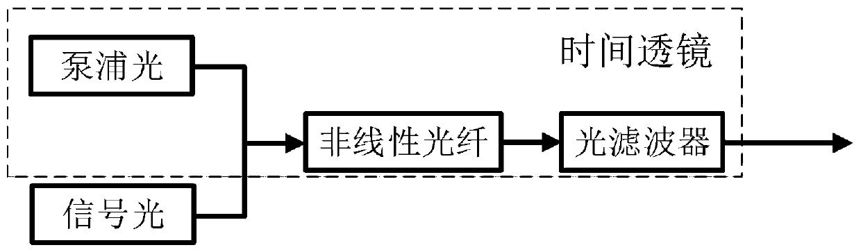
[0067] like Figure 7 As shown, in this embodiment, the waveform generation module is an arbitrary waveform generator, the jump variable control module is an adjustable optical attenuator, and the phase modulation module is a combination of a pump light source, an intensity modulator, a nonlinear optical fiber, and an optical filter .

[0068] First, the pump light source generates a single-wavelength pump laser, and the optical power of the pump laser is controlled by an adjustable optical attenuator; the arbitrary waveform generator performs equal-amplitude division and recombination of the standard parabolic drive signal to generate a split parabolic drive signal. The intensity modulator is used to modulate the intensity of the pump light, and the adjustable optical attenuator is adjusted so that the output optical signal of the intensity modulator is:

[0069]

[0070]

[0071] the s n =-(n-1)P 0

[0072] Wherein, 2N is the number of divisions, when N=1, the abov...


PUM


Abstract

The invention discloses a time lens implementation method. The method comprises the following steps that step 1, the left and right halves of a standard parabolic driving signal are equally divided into N parts, and the obtained 2N parts of signals are translated and aligned in the amplitude direction and then recombined to obtain a split parabolic driving signal; N is an integer greater than or equal to 2; step 2, the split parabolic drive signal is used for introducing a secondary phase in time for the signal light, and the jump variable of the secondary phase is controlled to be 2pi at thephase jump point. The invention also discloses a time lens implementation device and a photon Fourier transform system. Compared with the prior art, the method can achieve a high quality factor time lens by a simple and efficient structure.

Description

technical field [0001] The invention relates to the technical field of photon real-time Fourier transform, in particular to a method for realizing a time lens with a high quality factor. Background technique [0002] The concept of time lens comes from the duality of space and time. The so-called space-time duality refers to the similarity in the mathematical expression between the paraxial diffraction of the beam in free space and the dispersion propagation of narrow-band light pulses in the medium. Therefore, the effect of the lens in space on the beam can be extended to time. . The definition of time lens is a device that can introduce temporal secondary phase modulation to the input light pulse. Its inherent two parameters are aperture and time domain resolution: the aperture of time lens refers to the time domain that can be modulated The maximum pulse width, the time domain resolution of the time lens refers to the narrowest pulse width that can be obtained through t...

Claims


Application Information

Patent Timeline
Patent Type & Authority Patents(China)
IPC IPC(8): G02F1/01G02F1/365
CPCG02F1/0121G02F1/0123G02F1/0136G02F1/365
Inventor 朱丹张博文潘时龙陈文娟周涛钟欣张亚梅陈智宇雷震杜文浩
Owner NANJING UNIV OF AERONAUTICS & ASTRONAUTICS
Features
  • R&D
  • Intellectual Property
  • Life Sciences
  • Materials
  • Tech Scout
  • Unparalleled Data Quality
  • Higher Quality Content
  • 60% Fewer Hallucinations
Learn More