Energy feedback system applied to power generator and power generation system
An energy feedback and generator technology, applied in the direction of motor generator testing, electrical components, circuit devices, etc., can solve the problems of energy waste, large diesel consumption, etc., and achieve the effect of improving utilization and reducing testing costs
- Summary
- Abstract
- Description
- Claims
- Application Information
AI Technical Summary
Problems solved by technology
Method used
Image

Examples
Embodiment 1
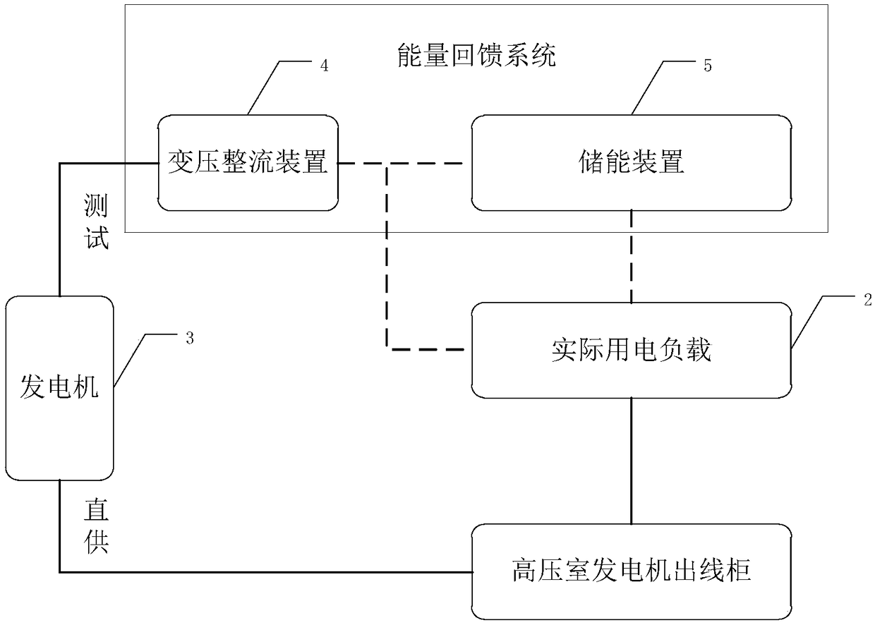
[0036] figure 2 A structural diagram of an energy feedback system applied to a generator provided by an embodiment of the present invention. Such as figure 2 As shown, the energy feedback system includes a transformer and rectifier device 4 for connecting with the output end of the generator, and is used to transform and rectify the alternating current output by the generator 3 to output direct current of a predetermined voltage. The transformer and rectifier device 4 is used for To be connected with the energy storage device 5 and / or the actual electric load 2 . figure 2 Dashed lines indicate optional connections.
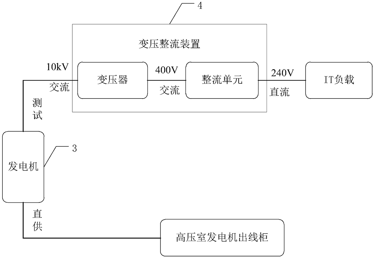
[0037] It should be noted that the function of the transformer and rectifier is to transform and rectify, so it must include a transformer and a rectifier unit. The transformer is used for voltage conversion, and the rectifier unit is used to adjust parameters such as power during the test process. The transformer can be a step-up transformer or a step-down ...
Embodiment 2
[0051] In the above embodiments, the transformer rectifier device can be connected with any one of the energy storage device and the actual electric load, or both; Powered separately. Figure 4 A structural diagram of another energy feedback system provided by an embodiment of the present invention. Such as Figure 4 As shown, in this embodiment, the electric energy finally output by the generator is connected to the mains grid to supply power to the actual electric load. In this case, the energy feedback system further includes: an inverter and transformer device 6 arranged between the transformer and rectifier device 4 and the actual electric load 2, used to transform and convert the direct current output by the transformer and rectifier device 4 The inverter is used to output alternating current of a predetermined voltage, and the output end of the inverter transformer device 6 is connected to the high-voltage mains incoming cabinet to be connected to the mains grid to su...
Embodiment 3
[0059] In the first embodiment, the transformer and rectifier device can be connected to any one of the energy storage device and the actual electric load, or both. In this embodiment, the transformer rectifier is connected to both the energy storage device and the actual electric load, and the energy storage device is also connected to the actual electric load. For details, see figure 2 .
[0060] Since in this embodiment, except that the energy storage device is connected to the actual electric load, the connection modes and working principles of other devices are the same as those in Embodiment 1, so details are not repeated here. In this embodiment, the purpose of connecting the energy storage device to the actual electric load is to consume the stored electric energy on the energy storage device. In a specific application scenario, the generator test takes half an hour, and the energy storage device and the actual power load are connected to the transformer rectifier de...
PUM
 Abstract
Description
Claims
Application Information
 - R&D Engineer
- R&D Manager
- IP Professional
- Industry Leading Data Capabilities
- Powerful AI technology
- Patent DNA Extraction
Browse by: Latest US Patents, China's latest patents, Technical Efficacy Thesaurus, Application Domain, Technology Topic.
© 2024 PatSnap. All rights reserved.Legal|Privacy policy|Modern Slavery Act Transparency Statement|Sitemap