Uniform gas supply device for vapor deposition furnace, and vapor deposition furnace

A technology of vapor deposition and gas supply device, applied in gaseous chemical plating, metal material coating process, coating and other directions, can solve the problems of many influencing factors, high control requirements, complicated operation and other problems, to ensure consistency, high Heating efficiency, the effect of ensuring uniformity

Active Publication Date: 2019-03-05
SUZHOU SICREAT NANOTECH CO LTD
View PDF5 Cites 0 Cited by
  • Summary
  • Abstract
  • Description
  • Claims
  • Application Information

AI Technical Summary

Problems solved by technology

[0005] Since the reaction gas rushes directly to the workpiece from the bottom of the deposition chamber, the impact force of the gas flow generated when it gushes out is relatively high, and the gas flow rate is relatively fast, which is not conducive to sufficient contact reaction with the workpiece, and is also easy to cause impact on the gas atmosphere in the deposition chamber; And after the reaction gas gushes out, it is easy to concentrate in the middle area of ​​the deposition chamber, resulting in uneven distribution of the reaction gas, which is not conducive to the adequacy of the contact between the workpiece near the wall of the deposition chamber and the reaction gas, and cannot guarantee the consistency of the product in the same deposition process sex
[0006] At the same time, the structure of an air inlet cannot adjust the supply of reaction gas at the corresponding position according to the difference in the coating quality of the product at different positions, and the adjustability is poor.
[0007] In addition, the conventional reaction gas supply pipeline usually introduces the carrier gas into the liquid reaction source heated by the water bath, and the evaporated reaction source is driven by the carrier gas into the deposition chamber. The calculation method is used to control, not the direct quantitative value. The supply of the reaction source is controlled by the temperature of the water bath, the gas pressure in the bubbling bottle, the vapor pressure of the organic metal source and other parameters. There are many influencing fact

Method used


Image

  • Uniform gas supply device for vapor deposition furnace, and vapor deposition furnace
  • Uniform gas supply device for vapor deposition furnace, and vapor deposition furnace
  • Uniform gas supply device for vapor deposition furnace, and vapor deposition furnace

Examples


Example Embodiment

[0046] The purpose, advantages and characteristics of the present invention will be illustrated and explained through the following non-limiting description of preferred embodiments. These embodiments are only typical examples of applying the technical solutions of the present invention, and any technical solutions formed by equivalent substitutions or equivalent transformations fall within the scope of protection of the present invention.

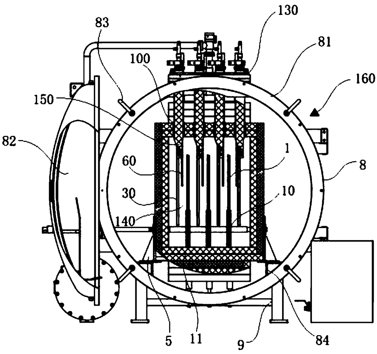
[0047] The present invention discloses a vapor deposition furnace 160, as attached image 3 As shown, a vacuum chamber 8 is included. The vacuum chamber 8 includes a cylindrical vacuum chamber body 81 and a sealed door 82 located at two circular openings of the vacuum chamber body 81. The sealed door 82 and the vacuum The chamber main body 81 is pivotally connected, and the sealed door 82 is preferably hermetically connected to the vacuum chamber main body 81 through four clamps 83 distributed in a rectangular shape.

[0048] As attached image...


PUM


Abstract

The invention discloses a uniform gas supply device for a vapor deposition furnace, and the vapor deposition furnace. The uniform gas supply device for the vapor deposition furnace comprises one or more T-shaped gas uniformizing pipelines, and the directions of gas outlet holes of the gas uniformizing pipelines are opposite to the ascending direction of reactive gas, and the gas outlet holes are back on to workpieces. According to the uniform gas supply device for the vapor deposition furnace, design is ingenious, by setting the directions of the gas outlet holes, the reactive gas can be gradually spread to the workpiece area after flowing out, the problems that when one gas outlet supplies gas to the workpieces directly, gas flow impact is prone to being caused, the reactive gas is proneto being concentrated in a certain area, and consequently the reactive gas is distributed nonuniformly are avoided, the supplying uniformity of the reactive gas can be ensured, and the quality of filmdeposition is improved advantageously.

Description

technical field [0001] The invention relates to the field of vapor deposition equipment, in particular to a uniform gas supply device for a vapor deposition furnace and a vapor deposition furnace. Background technique [0002] Chemical Vapor Deposition (CVD) refers to the process of introducing the gaseous or liquid reactant vapor and other gases required for the reaction into the deposition chamber, and a chemical reaction occurs on the substrate surface to form a thin film. [0003] The CVD chemical vapor deposition furnace uses the principle of chemical vapor deposition (Chemical Vapor Deposition) to heat the substances involved in the chemical reaction to a certain process temperature, and under the gravitational force generated by the vacuum pump pumping system, it is led to the deposition chamber for reaction and deposition. , to generate a new solid thin film substance. [0004] The traditional vertical CVD furnace adopts an air inlet at the bottom and an air outlet ...

Claims


Application Information

Patent Timeline
IPC IPC(8): C23C16/455C23C16/458
CPCC23C16/45561C23C16/4588
Inventor 鞠涛张立国李哲范亚明张泽洪张宝顺
Owner SUZHOU SICREAT NANOTECH CO LTD
Why Eureka
Try Eureka