A real-time transmission device for noise measurement data

A technology of real-time transmission and noise measurement, applied in the direction of measuring devices, using electrical devices, measuring ultrasonic/sonic waves/infrasonic waves, etc., can solve problems such as attenuation, signal transmission electromagnetic noise interference, etc., to reduce electromagnetic noise interference, improve accuracy, improve The effect of anti-interference

Active Publication Date: 2020-04-14
河南鑫安利职业健康科技有限公司
View PDF7 Cites 0 Cited by
  • Summary
  • Abstract
  • Description
  • Claims
  • Application Information

AI Technical Summary

Problems solved by technology

[0004] In view of the above situation, in order to overcome the defects of the prior art, the purpose of the present invention is to provide a real-time transmission device for noise measurement data, which has the characteristics of ingenious design and humanized design, and effectively solves the problem of low-frequency transmission of the transmitter and signal transmission process. Susceptible to electromagnetic noise interference and attenuation problems

Method used


Image

  • A real-time transmission device for noise measurement data
  • A real-time transmission device for noise measurement data
  • A real-time transmission device for noise measurement data

Examples


Embodiment 1

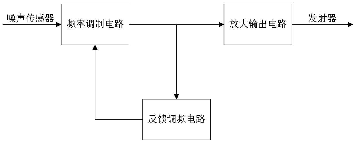
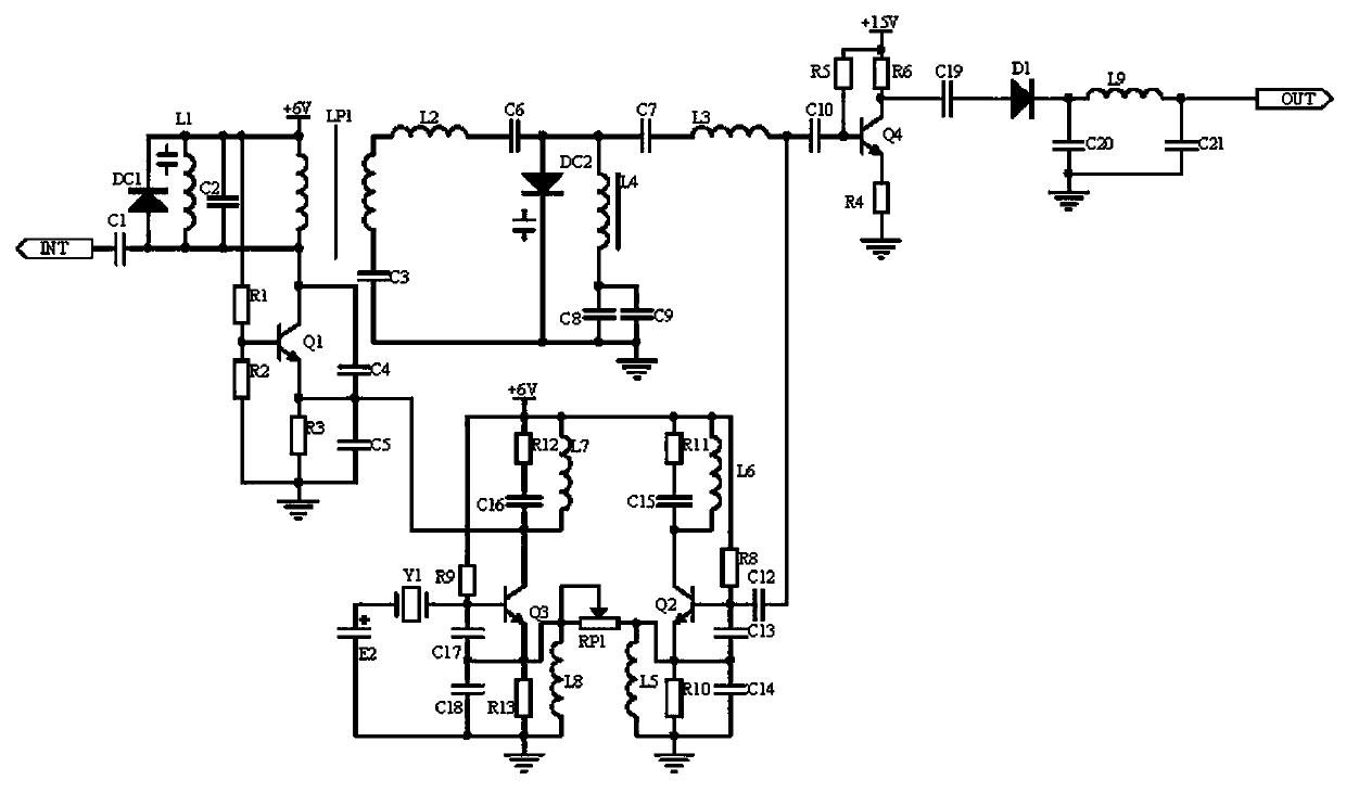
[0014] Embodiment 1, a real-time transmission device for noise measurement data, including a noise sensor and a transmitter, the coal mine noise information measured by the noise sensor is transmitted to the noise monitoring server through the transmitter, so as to realize online monitoring and real-time transmission. A frequency modulation circuit, a feedback frequency modulation circuit, and an amplifying output circuit are also connected between the devices. The frequency modulation circuit receives the 200-1000Hz frequency signal output by the noise sensor of the GSD130 type, and passes through the varactor diode DC1, the capacitor C1, and the inductor L1. The composed adjustable resonant circuit resonates to generate a resonant frequency, obtains the frequency signal corresponding to the measurement noise, and then enters the 450MHz oscillating frequency generated by the LC oscillator with the core of the triode Q1, resistor R1-resistor R3, and oscillating coil LP1 for modu...

Embodiment 2

[0015] Embodiment 2, on the basis of Embodiment 1, the 200-1000 Hz frequency signal output by the noise sensor model GSD130 received by the frequency modulation circuit is passed through an adjustable resonant circuit composed of a varactor diode DC1, a capacitor C1, and an inductance L1 Carry out resonance to generate a resonant frequency, obtain the frequency signal corresponding to the measurement noise, and then enter the 450MHz oscillation frequency generated by the LC oscillator with the core of the triode Q1, resistor R1-resistor R3, and oscillating coil LP1 for modulation, where resistor R1 and resistor R2 are triode The base bias resistor of Q1, adjusting the value of the oscillating coil LP1 can adjust the oscillating frequency of the LC oscillator. After modulation, the signal passes through a varactor diode frequency multiplier composed of a varactor diode DC2, an inductor L2-inductor L4, and a capacitor C6-capacitor C9. After 2 frequency doubling, it is modulated t...

Embodiment 3

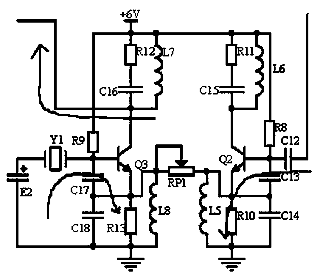
[0016]Embodiment 3, on the basis of Embodiment 2, the feedback frequency modulation circuit receives the output signal of the frequency modulation circuit, and uses the differential principle to calculate the frequency multiplier through the double-ended input and single-ended output differential circuit with transistors Q2 and Q3 as the core. The resonant frequency of the output signal (specifically, the output signal is coupled to the base of the transistor Q2 through the capacitor C12 after frequency multiplication, and the LC parallel resonant circuit composed of the emitter capacitor C14 of the transistor Q2 and the inductor L5 generates a resonant frequency. The capacitor C13 is connected in series with the capacitor C14. Pad capacitor, resistor R8 is the base bias resistor, resistor R11, capacitor C15, and inductor L6 provide a stable bias voltage for the collector) and the resonant frequency of the reference frequency signal (specifically, the 900MHz crystal oscillator Y...


PUM


Abstract

The invention discloses a real-time transmission device for noise measurement data. A frequency modulation circuit resonates with a received 200-1000Hz frequency signal output by a noise sensor with amodel GSD130 through a resonance circuit to generate a resonance frequency. Then the device obtains a frequency signal corresponding to measurement noise and modulates the 450MHz oscillation frequency generated by an LC oscillator with a transistor Q1 and an oscillation coil LP1 as the core. Then the modulated signal is multiplied by two times through a frequency multiplier, and one path of the modulated signal enters the feedback frequency modulation circuit and the frequency offset signal of the resonant frequency of the output signal and the resonant frequency of the reference frequency signal is multiplied back to the LC oscillator by the differential circuit of the transistor Q2 and Q3 as the core, so that the modulated frequency signal is tailored to the best mine transmission frequency-900MH. The other path enters the amplification output circuit and is processed by amplitude amplification, unidirectional conduction, and pi-type filter circuit, and then applied to the transmitter. The real-time transmission device for noise measurement data effectively solves the problems that the transmitter is easy to be interfered and attenuated by electromagnetic noise in the processesof low-frequency band transmission and signal transmission of the transmitter.

Description

technical field [0001] The invention relates to the technical field of coal mine and noise measurement, in particular to a real-time transmission device for noise measurement data. Background technique [0002] Noise can hinder people's work, conversation, rest and sleep, damage people's hearing, and cause people's psychological, physiological and pathological reactions, especially in coal mines. The noise hazard is even worse. Employees exposed to this environment for a long time will cause noise-induced hearing loss. Therefore, it is necessary to measure and monitor the noise, and then take noise reduction protection measures. At present, noise sensors are mainly used to measure coal mine noise information, which is transmitted to the computer through communication cables or transmitters, and then transmitted to the monitoring center server by the computer in real time through the network. For remote monitoring, since it is inconvenient to lay communication cables in coal ...

Claims


Application Information

Patent Timeline
Patent Type & Authority Patents(China)
IPC IPC(8): G01H11/06
CPCG01H11/06
Inventor 方希景毛春丽王艳娇冯艳花杨现林孙山生郭志军马会涛赵昆南
Owner 河南鑫安利职业健康科技有限公司
Why Eureka
Try Eureka