Cleaning coating machine and cleaning coating method

A coating machine and plasma cleaning technology, applied in sputtering plating, ion implantation plating, vacuum evaporation plating, etc., can solve the problems of poor hydrophilicity and poor primary adhesion, and achieve good hydrophilicity, good The effect of technical effects

Pending Publication Date: 2019-03-12
苏州凯瑞纳米科技有限公司
View PDF1 Cites 1 Cited by
  • Summary
  • Abstract
  • Description
  • Claims
  • Application Information

AI Technical Summary

Problems solved by technology

[0006] One of the technical problems to be solved by the present invention is the technical problem of low dyne value and poor hydrophilicity and poor adhesion on the surface of the workpiece to be plated after plasma cleaning in the prior art. A cleaning and coating machine is provided. The dyne value of the surface of the workpiece to be coated after machine plasma cleaning is relatively high, and there is good adhesion between the coated film layer and the workpiece to be coated

Method used


Image

  • Cleaning coating machine and cleaning coating method
  • Cleaning coating machine and cleaning coating method
  • Cleaning coating machine and cleaning coating method

Examples


Embodiment 1

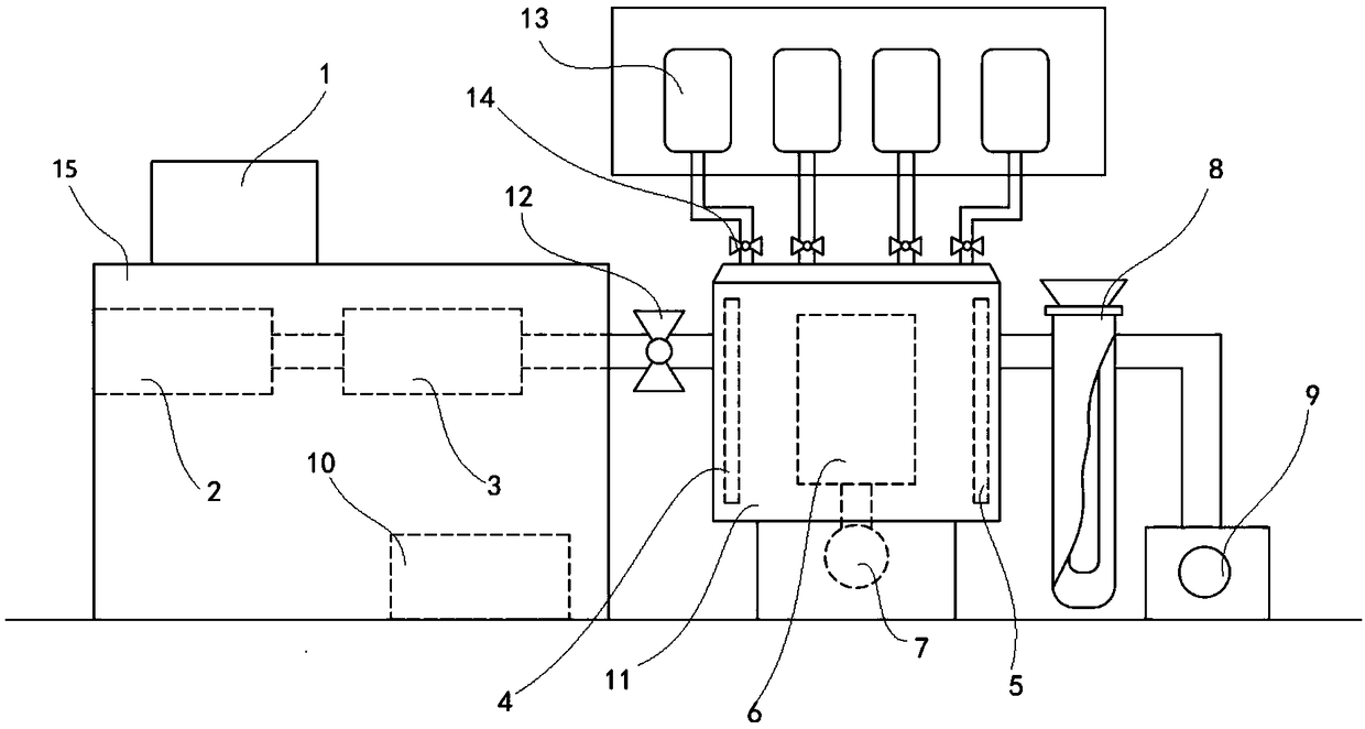
[0023] Such as figure 1 As shown, embodiment 1 discloses a specific embodiment of a cleaning coating machine, which is used to coat a parylene film (i.e. parylene film) on a piece to be coated, which includes: sequentially connected powder gasifiers 2. The high temperature cracking furnace 3, the processing chamber 11, the cold trap 8, the vacuum pump 9, 4 groups of gas tank groups and the central controller 1, wherein the high temperature cracking furnace 3 and the processing chamber 11 are connected through a powder valve 12, and the powder The body valve 12 is a solenoid valve, and the processing chamber 11 is provided with a rotatable bracket assembly and a plasma cleaning assembly for placing the parts to be plated. Each group of gas tank groups includes a gas tank 13 and a gas valve 14. The gas tank 13 The corresponding gas valve 14 communicates with the inside of the processing chamber 11 , and the gas valve 14 is a solenoid valve. Argon, oxygen, hydrogen and nitrogen ...

Embodiment 2

[0032] Such as figure 1 As shown, embodiment 2 discloses a specific embodiment of a cleaning and coating method, which uses the cleaning and coating machine disclosed in embodiment 1, and the method specifically includes the following steps:

[0033] a) Place the piece to be plated on the rotatable bracket assembly of the processing chamber 11, place the coating material in the powder gasification furnace 2, and close the powder valve 12 communicating between the high temperature cracking furnace 3 and the processing chamber 11;

[0034] b) start the cold trap 8 and the vacuum pump 9 to evacuate the processing chamber 11, and the pressure in the processing chamber 11 reaches 15-50 Pa;

[0035] c) Start the plasma cleaning component to clean the parts to be plated in the processing chamber 11, and the cleaning time is 1 to 30 minutes;

[0036] d) After closing the plasma cleaning assembly, open the powder valve 12, and control the pressure in the processing chamber 11 at 5-30P...

Embodiment 3~4

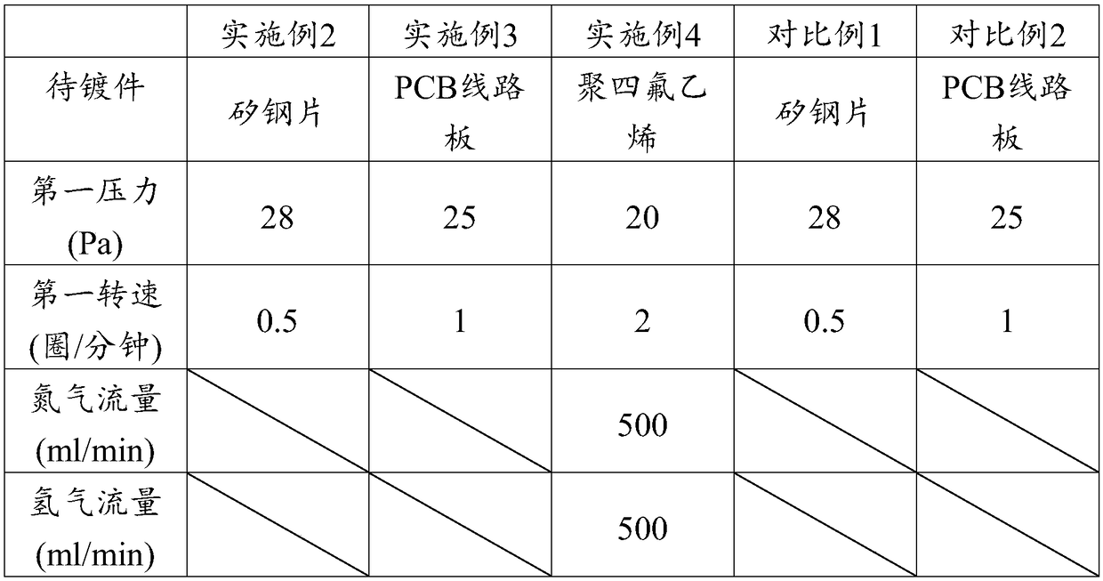
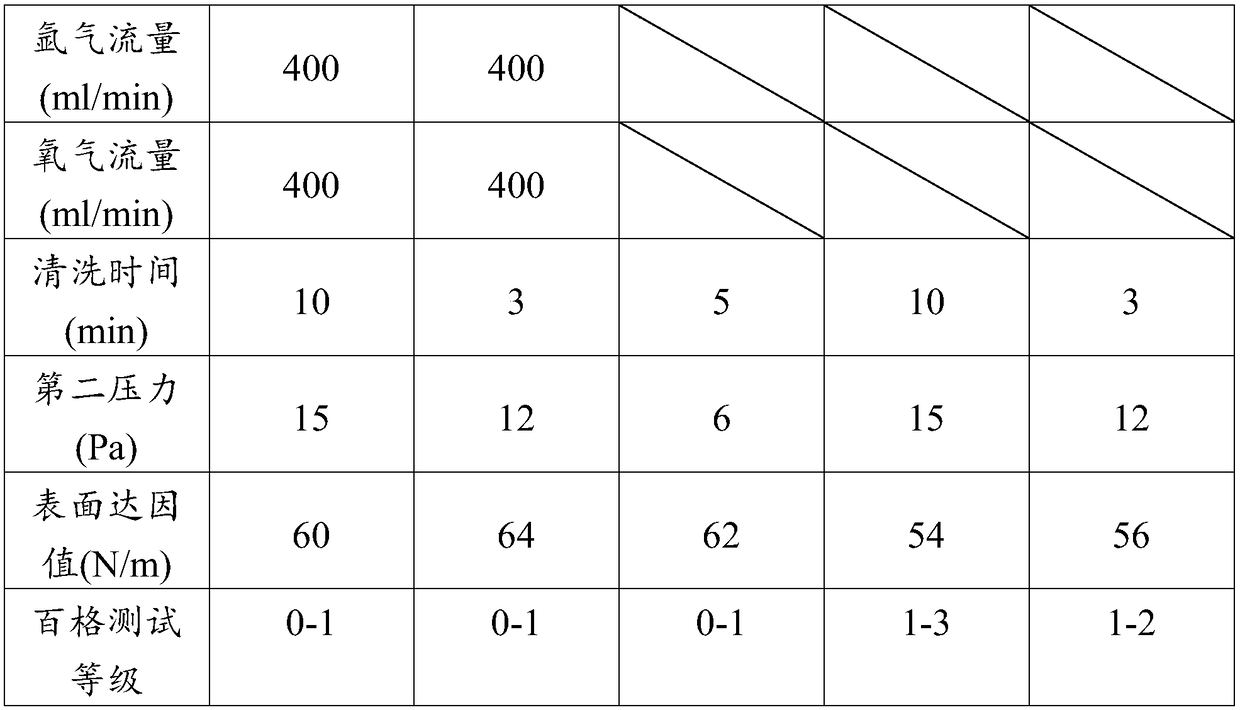
[0048] The cleaning and coating method in embodiment 2 is adopted below to plate parylene coating film on other different materials to be coated, respectively as embodiments 3~4, the experimental parameters of embodiments 3~4, the workpiece to be coated after plasma cleaning The surface dyne values ​​and the properties of the obtained coated products are listed in Table 1 below.


PUM


Abstract

The invention relates to a cleaning coating machine and a cleaning coating method. The cleaning coating machine and the cleaning coating method mainly solves the problem that the surface of a unit tobe plated after plasma cleaning is low in dyne value in the prior art. The cleaning coating machine comprises a powder gasification furnace, a high temperature pyrolysis furnace, a processing chamber,a cold trap, a vacuum pump, a plasma cleaning assembly, gas tank groups and a central controller, wherein each gas tank group is composed of a gas tank and a gas valve, the gas tanks communicate withthe processing chamber through the gas valves, and the central controller is connected with the powder gasification furnace, the high temperature pyrolysis furnace, a powder valve, a rotatable bracket assembly, the cold trap, the vacuum pump and the plasma cleaning assembly. The plasma cleaning assembly comprises a plasma controller, a plasma positive plate and a plasma negative plate, wherein the plasma positive plate and the plasma negative plate are arranged on both sides of the rotatable bracket assembly. The plasma controller is connected with the central controller, the plasma positiveplate, the plasma negative plate and the gas valve. The cleaning coating machine and the cleaning coating method well solve the problems and can be applied to the industrial production of parylene coating.

Description

technical field [0001] The invention relates to a cleaning coating machine and a cleaning coating method. technical background [0002] With the improvement of the quality requirements of electronic products for coating, it is necessary to add a plasma cleaning process to clean the product before the coating process to improve the coating quality. The existing vacuum coating machine and plasma cleaning machine for parylene coating are two independent equipment, and there are the following problems in the cooperation process: [0003] 1. It is necessary to put the parts to be plated into the cavity of the plasma cleaning machine to evacuate the surface of the product after vacuuming, and then restore the normal pressure to take out the parts to be plated and put them into the cavity of the vacuum coating machine and then evacuate to the specified vacuum value Start coating. Multiple vacuuming operations take a long time, which affects the processing efficiency, and with the...

Claims


Application Information

Patent Timeline
Patent Type & Authority Applications(China)
IPC IPC(8): C23C14/02C23C14/24
CPCC23C14/022C23C14/24
Inventor 钦晔
Owner 苏州凯瑞纳米科技有限公司
Why Eureka
Try Eureka