Integrated centrifugal machine dynamic balancing device and balancing method

A centrifuge and integrated technology, applied in the direction of centrifuges, etc., can solve the problems of unsafe factors, difficulty in precise control, lack of test pieces, etc., and achieve the effect of simple structure, small and compact structure, and light weight

Active Publication Date: 2019-03-15
GENERAL ENG RES INST CHINA ACAD OF ENG PHYSICS
View PDF12 Cites 9 Cited by
  • Summary
  • Abstract
  • Description
  • Claims
  • Application Information

AI Technical Summary

Problems solved by technology

The static balancing method using the counterweight type or electric drive mobile counterweight will not change again once it is installed or adjusted, and it does not have the ability to balance the unbalanced force on the test piece under the working state of the centrifuge
[0007] 2. The design and selection of motor-driven static/dynamic trim methods are difficult
[0008] The motor-driven trim device needs to bear at least dozens of G centrifugal loads during the working process of the centrifuge, and it is difficult to select a motor that works reliably in a strong centrifugal field environment, and the core components such as the screw and nut of the transmission mechanism are even more difficult. It is difficult to meet the requirements of high centrifugal field, and the design of the trim device is limited by many factors such as the speed of the centrifuge and the installation position of the device
[0009] 3. The response speed of the hydraulic drive mode is slow, the stroke is limited, and the trimming ability is limited
[0010] Although the hydraulic drive method has a large load capacity, the response speed of the hydraulic drive process is relatively slow and the stroke is limited compared with the motor drive and water drive. Heavy mode trim ability is very limited
[0011] 4. With the water-driven dynamic trim method, it is difficult to precisely control the water flow, and the trim accuracy is limited. In a strong centrifugal field, it is easy to produce negative effects such as overshoot
[0012] D

Method used


Image

  • Integrated centrifugal machine dynamic balancing device and balancing method
  • Integrated centrifugal machine dynamic balancing device and balancing method
  • Integrated centrifugal machine dynamic balancing device and balancing method

Examples


Embodiment 1

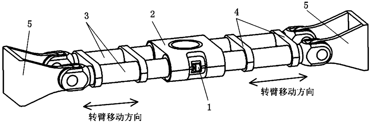
[0053] Example 1, such as figure 1 as shown,

[0054] Integral centrifuge dynamic trim device, the centrifuge includes a rotary arm support 2 and a tension shaft 3, the tension shaft 3 is movable through the internal installation of the rotary arm support 2, and the tension shaft 3 is symmetrical based on the vertical axis of the rotary arm support 2 distribution, dynamic trim includes:

[0055] The unbalanced force measurement and motion control part 1 is used for the unbalanced force measurement of the centrifuge and the unbalanced force compensation and adjustment.

[0056] The centrifuge also includes a positioning ring 4 and a hanging basket 5, and the sample and the static counterweight are respectively installed in the hanging baskets 5 at both ends of the rotating arm of the centrifuge.

[0057] On the premise that the tension shaft 3 is movably installed through the inside of the rotating arm support 2, the measurement of the unbalanced force of the centrifuge and t...

Embodiment 2

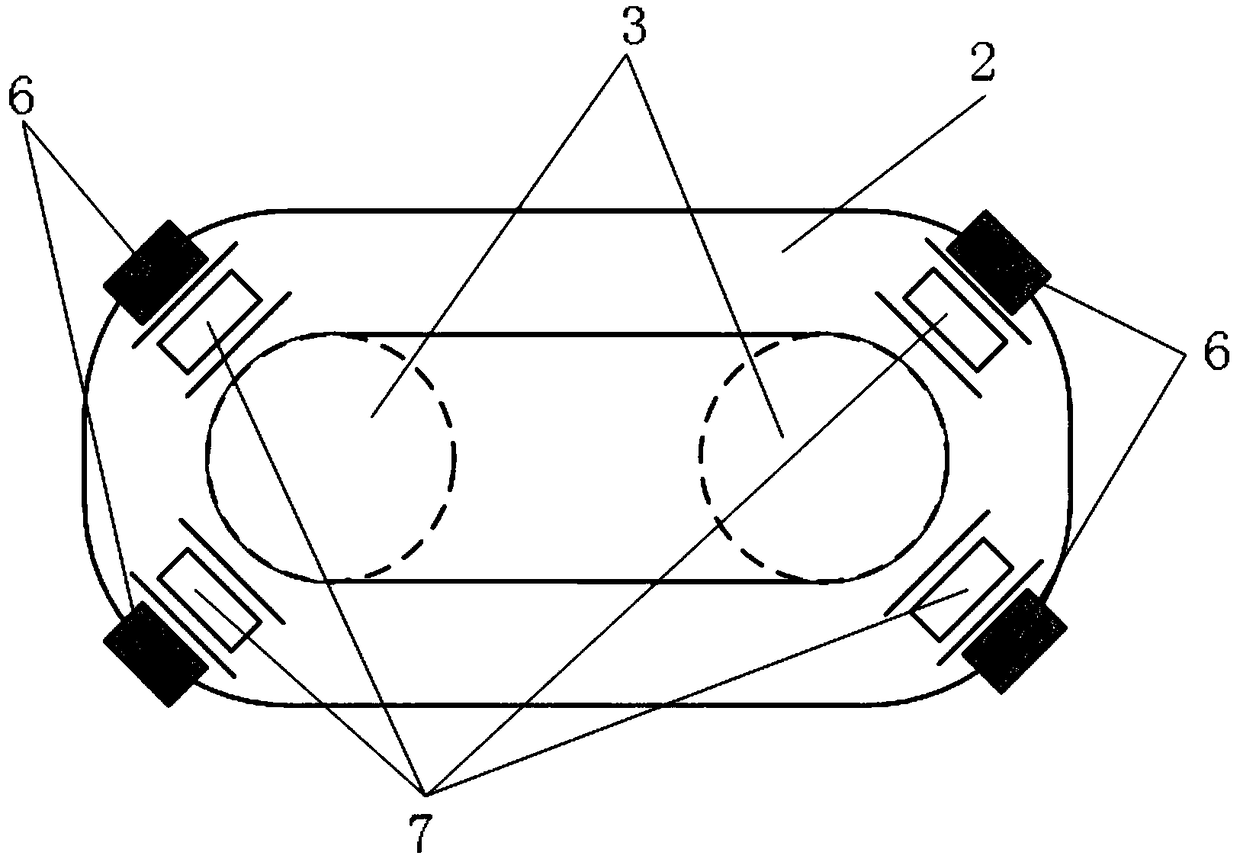
[0058] Example 2, such as Figure 4 with Image 6 as shown,

[0059] The difference between this embodiment and Embodiment 1 is that the unbalanced force measurement and motion control component 1 includes:

[0060] Servo two-way hydraulic cylinder 11; the servo two-way hydraulic cylinder 11 is fixedly installed on the tension shaft 3, a groove is provided on the inner side of the swing arm support 2 in contact with the tension shaft 3, and the hydraulic rod of the servo two-way hydraulic cylinder 11 is placed in the groove , and acts on the two directions of the pivot arm support 2;

[0061] Two load cells 12; the two load cells 12 are installed at both ends of the hydraulic rod of the servo two-way hydraulic cylinder 11, and are used to collect the unbalanced force of the rotating arm of the centrifuge in the working state;

[0062] Two linear displacement sensors 13; two linear displacement sensors 13 are installed on the servo two-way hydraulic cylinder 11 and placed in...

Embodiment 3

[0064] Example 3, such as figure 1 with Image 6 as shown,

[0065] The difference between this embodiment and embodiment 1 or embodiment 2 is that: there are two unbalanced force measurement and motion control components 1 , which are distributed symmetrically based on the tension axis 3 ; and there are two grooves provided on the pivot arm support 2 .

[0066] Such as Figure 5 Shown is the working principle diagram of the hydraulic motion system in this embodiment, the servo two-way hydraulic cylinder 11 is driven by the servo hydraulic pump 115, and realizes the hydraulic pressure to the two servo two-way hydraulic cylinders 11 through the electronically controlled flow control valve 113 controlled by the host computer. Synchronous and precise control of oil volume, a relief valve 114 is also set on the oil circuit between the servo hydraulic pump 115 and the two electronically controlled flow control valves 113, and the two-way expansion and contraction of the servo two...


PUM


Abstract

The invention discloses an integrated centrifugal machine dynamic balancing device and balancing method. According to the integrated centrifugal machine dynamic balancing device and the integrated centrifugal machine dynamic balancing method, balancing capacity is only related to self weight of a rocker arm system and axial translation displacement of rocker arms, and is not limited by aspects like capacity of a centrifugal machine, mass of movable clump weights and moving distance; the speed of a centrifugal field is only dozens of times that of gravitational acceleration due to mounting positions, the requirement on G value tolerance capacity of the entire balancing device is not high, and the device can reliably operate under a large-G value working condition; the entire dynamic balancing adjusting process of the centrifugal machine rocker arms is a double-closed loop control process and comprises a position closed loop feedback control inner ring between rocker arm practical offsettranslation and motion control of a hydraulic servo system and a force feedback closed loop control outer ring composed of rocker arm unbalanced force monitoring and unbalanced force control; and safe, reliable and accurate operation of an unbalanced force dynamic balancing system can be effectively guaranteed through a double-closed loop control method, and real-time updating, on-line monitoringand dynamic balancing can be carried out on unbalanced force under operation of the centrifugal machine.

Description

technical field [0001] The invention belongs to the technical field of dynamic trimming of centrifuges, and in particular relates to a dynamic trimming device and a trimming method of an integral centrifuge. Background technique [0002] All rotating machinery should be as balanced as possible. The unbalanced force will cause dynamic load during the operation of the centrifuge and cause equipment vibration, resulting in reduced system operation stability and accuracy, increased motion noise, accelerated wear of moving parts, and abnormal rotors. Running, life shortening and even host overturning seriously affect the operation safety of the whole centrifuge. Therefore, it is necessary to balance the unbalanced force no matter before or during the operation of the centrifuge. [0003] At present, most domestic centrifuges are trimmed using a static trim method. That is: based on the principle of moment balance, in the non-working state, the counterweight of a certain mass is...

Claims


Application Information

Patent Timeline
IPC IPC(8): B04B9/14B04B15/00
CPCB04B9/14B04B15/00
Inventor 陈磊付兴张志强成永博洪建忠
Owner GENERAL ENG RES INST CHINA ACAD OF ENG PHYSICS
Why Eureka
Try Eureka