A method for forging/additive composite manufacturing of amorphous alloy parts

A technology of amorphous alloy and manufacturing method, which is applied in the field of forging/additive composite manufacturing of amorphous alloy parts, which can solve the problems of poor overall performance, size limitation, poor interface connection performance, etc., achieve fast sintering speed and increase density , the effect of low sintering temperature

Active Publication Date: 2019-10-25
HUAZHONG UNIV OF SCI & TECH
View PDF9 Cites 0 Cited by
  • Summary
  • Abstract
  • Description
  • Claims
  • Application Information

AI Technical Summary

Problems solved by technology

[0007] In view of the above defects or improvement needs of the prior art, the present invention provides a forging / additive composite manufacturing method for amorphous alloy parts, which fully combines the current status of manufacturing technology for amorphous alloy parts, traditional manufacturing methods, and additive manufacturing technology. According to the characteristics and aerospace application requirements, the manufacturing method of amorphous alloy parts is redesigned. First, the powder sintering technology is used to make the pre-forging billet from the amorphous alloy powder material, and then the pre-forging billet is placed in closed forging Closed hot die forging is carried out in the mold to obtain the main structure of the amorphous alloy part. Finally, the energy field-assisted additive manufacturing technology is used to process the main structure on the main structure to process a relatively small fine structure or a structure that cannot be formed by forging, and correspondingly obtain A forging / additive composite manufacturing method for large-scale, complex amorphous alloy parts is proposed, especially the interface connection performance between the main structure of the amorphous alloy and the local fine structure is strengthened and improved, thereby solving the problem of amorphous alloy parts Technical problems such as size limitation, shape limitation, poor interface connection performance between forging and additive fine structure and poor overall performance in manufacturing

Method used


Image

  • A method for forging/additive composite manufacturing of amorphous alloy parts
  • A method for forging/additive composite manufacturing of amorphous alloy parts
  • A method for forging/additive composite manufacturing of amorphous alloy parts

Examples


Embodiment 1

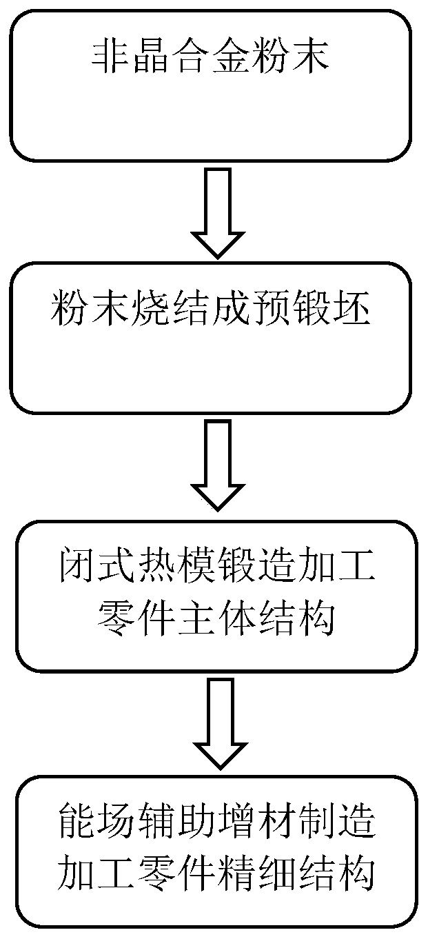
[0063] figure 1 It is a flow chart constructed according to an amorphous alloy part forging / additive composite manufacturing method of the present invention, such as figure 1 As shown, it includes the following steps:

[0064] (1) Choose Zr with a particle size of 35 μm prepared by vacuum induction inert gas atomization technology 55 Cu 25 Al 10 Ni 10 Amorphous alloy powder is made into pre-forged blank. Zr 55 Cu 25 Al 10 Ni 10 The critical dimension of the formation of amorphous alloy is greater than 10mm, and the glass transition temperature T g is 652K, the initial crystallization temperature T x is 757K, the liquidus temperature T L is 1121K, supercooled liquid phase interval ΔT x =T x -T g =105K, thermoplastic forming ability index S=ΔT x / (T L -T g )=0.224, it has good amorphous forming ability. Firstly, put the selected amorphous alloy powder into the sheath, and press it into a cold compact by cold isostatic pressing technology. The material used is ...

Embodiment 2

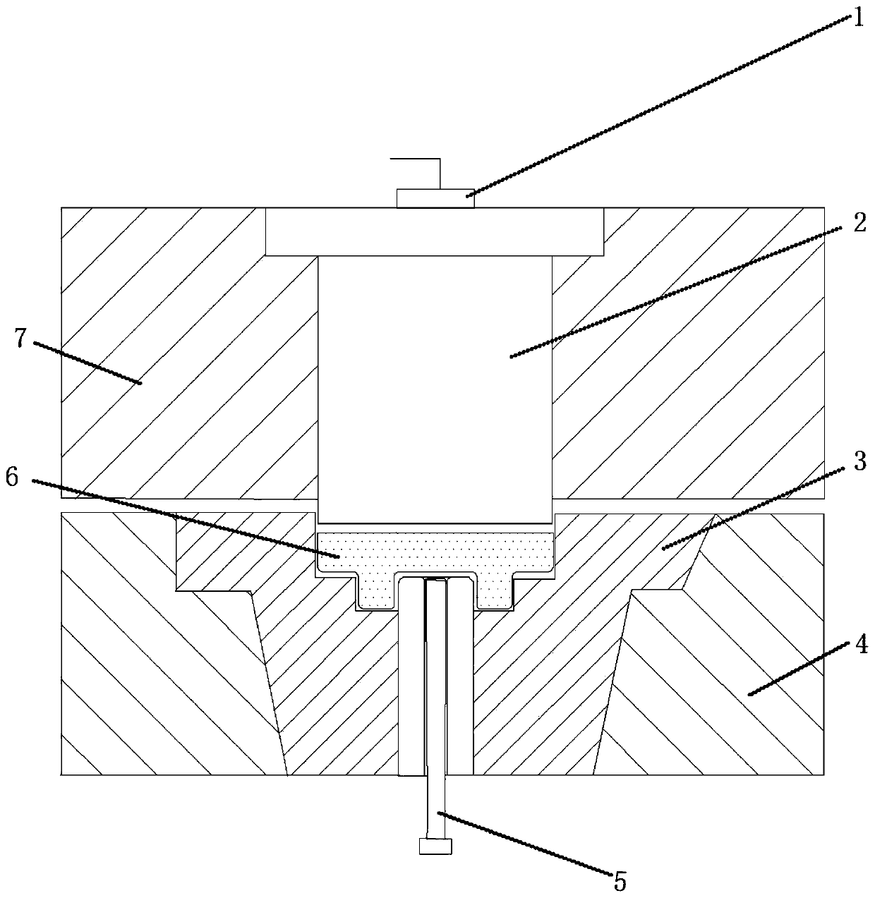
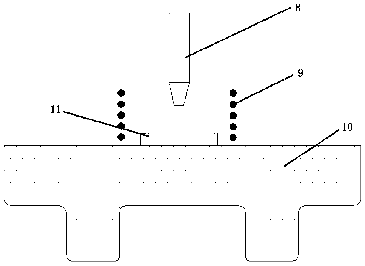
[0069] This embodiment is used to prepare an amorphous part with low internal stress requirements and subjected to alternating loads. When preparing this part, the same method as in Example 1 is used, and the amorphous alloy powder material is first made into a pre-forged billet by using powder sintering technology. , and then put the pre-forged billet in a closed forging die for closed hot die forging to obtain the main structure of the amorphous alloy part. Then, the ultra-high frequency strong pulse square wave assisted arc additive manufacturing technology is used to add materials to the main structure of the part to prepare fine structures.

[0070] Figure 4 It is a principle diagram of an ultra-high frequency strong pulse square wave assisted arc additive manufacturing method constructed according to a preferred embodiment of the present invention. Among them, 12-arc welding torch, 13-wire feeding mechanism, 16-current controller. Different pulse square wave currents ...

Embodiment 3

[0073] This embodiment is used to prepare amorphous parts with higher requirements on mechanical properties. When preparing the parts, the same method as in Example 1 is used to make the pre-forged billet from the amorphous alloy powder material by powder sintering technology, and then the pre-forged billet Place in a closed forging die for closed hot die forging to obtain the main structure of the amorphous alloy part. Then high-frequency micro-hammer forging assisted laser additive manufacturing technology.

[0074] Figure 7 Shown is a schematic diagram of an ultrasonic frequency micro-forging assisted laser additive manufacturing method constructed according to a preferred embodiment of the present invention. Among them, 14-micro-forging head, 15-piezoelectric ceramic vibration generator. First turn on the control power supply, and generate ultrasonic frequency vibration with the help of a piezoelectric ceramic vibration generator. The path of the micro-forging head 14 is ...


PUM

PropertyMeasurementUnit
critical dimensionaaaaaaaaaa
elastic limitaaaaaaaaaa
particle diameteraaaaaaaaaa

Abstract

The invention belongs to the technical field of thermoplastic forming and additive manufacturing of amorphous alloys, and specifically relates to a forging / additive composite manufacturing method of amorphous alloy parts, which first uses powder sintering technology to make amorphous alloy powder materials into pre-forged billets, Then place the pre-forged blank in a closed forging die for closed hot die forging to obtain the main structure of the amorphous alloy part. Finally, the energy field-assisted additive manufacturing technology is used on the main structure to process fine parts with relatively small sizes. structure, or some structures that cannot be formed by forging, such as thin-walled ribs, hollow shells, conformal cooling channels, etc. Correspondingly, a forging / additive composite manufacturing method for large-scale and complex amorphous alloy parts is obtained, especially the interface connection performance between the main structure of the amorphous alloy and the local fine structure is strengthened and improved.

Description

technical field [0001] The invention belongs to the technical field of thermoplastic forming and additive manufacturing of amorphous alloys, and in particular relates to a forging / additive composite manufacturing method of amorphous alloy parts. Background technique [0002] With the rapid development of the aerospace field, people's performance requirements for aerospace equipment continue to increase. At present, the forming and manufacturing of some large-scale aerospace equipment, such as vehicles, satellites, spaceships, and deep space probes, is constantly developing in the direction of lightweight, integrated, complex, and high-performance. The processing difficulty of aerospace components such as engine disks, shaft parts, turbine casings, landing gears, etc. is increasing. These complex structures are machined, cast, forged or difficult or costly to manufacture. The traditional manufacturing method based on machining combined with welding and assembly is not only ...

Claims


Application Information

Patent Timeline
Patent Type & Authority Patents(China)
IPC IPC(8): B22F3/04B22F3/105B22F3/24B33Y10/00B21J5/00B21J5/02
CPCB21J5/002B21J5/025B22F3/04B22F3/105B22F3/24B33Y10/00B22F2998/10B22F10/00B22F10/36B22F12/43B22F10/25B22F10/28Y02P10/25
Inventor 王新云龚攀丁华平邓磊金俊松
Owner HUAZHONG UNIV OF SCI & TECH
Why Eureka
Try Eureka