A laser additive manufacturing method for high-speed train brake discs
A laser additive, high-speed train technology, applied in additive manufacturing, additive processing, energy efficiency improvement, etc., can solve the problems of unstable casting quality, cumbersome brake disc process, poor casting process, etc., to avoid residual stress. Larger, avoids overall weight gain, reduces stress concentration effects
- Summary
- Abstract
- Description
- Claims
- Application Information
AI Technical Summary
Problems solved by technology
Method used
Image

Examples
Embodiment 1
[0045] A laser additive manufacturing method for a brake disc of a high-speed train, the steps of which are as follows:
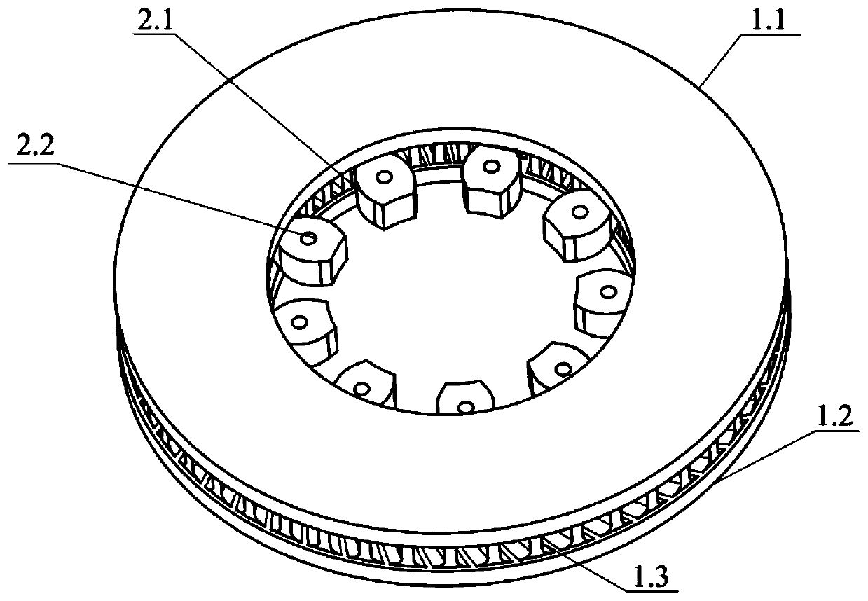
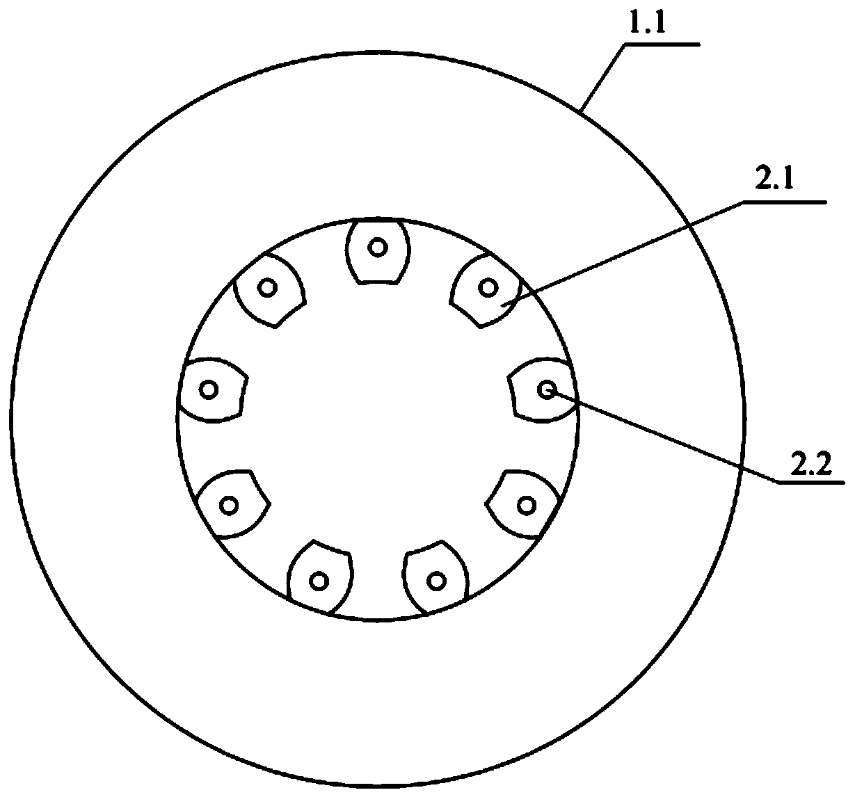
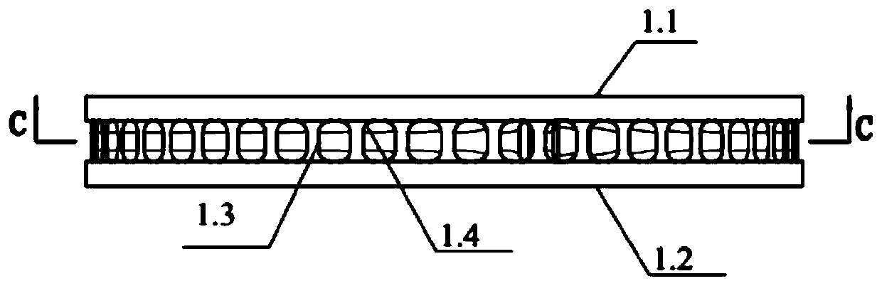
[0046] s1. Design and establish the three-dimensional model of the brake disc through drawing software, such as Figure 1 to Figure 4 As shown, the brake disc includes a brake disc main body with a hole in the disc body and a mounting hole seat 2.1 uniformly arranged radially inside the brake disc main body. The coaxial annular disk body (upper annular disk body 1.1 and lower annular disk body 1.2) of the hole in the body and sandwiched between the two annular disk bodies (upper annular disk body 1.1 and lower annular disk body 1.2) The heat dissipation ribs 1.3 are evenly arranged, and the installation hole seat 2.1 is provided with a mounting hole 2.2; the heat dissipation ribs 1.3 are one end close to the ring disc body (the upper ring disc body 1.1 and the lower ring disc body 1.2) ring, the other end is close to the circular arc strip structure of the...
Embodiment 2
[0056] A laser additive manufacturing method for a brake disc of a high-speed train, the steps of which are as follows:
[0057] s1. Design and establish a three-dimensional model of the brake disc through drawing software. The brake disc includes a brake disc body with a hole in the disc body and a mounting hole seat 2.1 uniformly arranged radially on the inner side of the brake disc body. The main body of the brake disc is composed of two upper and lower coaxial annular discs (upper annular disc 1.1 and lower annular disc 1.2) with disc holes in the upper and lower discs and clamped between the two annular discs (upper annular disc Body 1.1 and the lower circular disc body 1.2) composed of uniformly arranged heat dissipation ribs 1.3, the mounting hole seat 2.1 is provided with mounting holes 2.2; one end of the heat dissipation ribs 1.3 is close to the circular disc body (upper circular Disk body 1.1 and lower ring disk body 1.2) the inner ring, the other end is close to th...
Embodiment 3
[0066] A laser additive manufacturing method for a brake disc of a high-speed train, the steps of which are as follows:
[0067] s1. Design and establish a three-dimensional model of the brake disc through drawing software. The brake disc includes a brake disc body with a hole in the disc body and a mounting hole seat 2.1 uniformly arranged radially on the inner side of the brake disc body. The main body of the brake disc is composed of two upper and lower coaxial annular discs (upper annular disc 1.1 and lower annular disc 1.2) with disc holes in the upper and lower discs and clamped between the two annular discs (upper annular disc Body 1.1 and the lower circular disc body 1.2) composed of uniformly arranged heat dissipation ribs 1.3, the mounting hole seat 2.1 is provided with mounting holes 2.2; one end of the heat dissipation ribs 1.3 is close to the circular disc body (upper circular Disk body 1.1 and lower ring disk body 1.2) the inner ring, the other end is close to th...
PUM
| Property | Measurement | Unit |
|---|---|---|
| Outer diameter | aaaaa | aaaaa |
| Thickness | aaaaa | aaaaa |
Abstract
Description
Claims
Application Information
 - R&D
- Intellectual Property
- Life Sciences
- Materials
- Tech Scout
- Unparalleled Data Quality
- Higher Quality Content
- 60% Fewer Hallucinations
Browse by: Latest US Patents, China's latest patents, Technical Efficacy Thesaurus, Application Domain, Technology Topic, Popular Technical Reports.
© 2025 PatSnap. All rights reserved.Legal|Privacy policy|Modern Slavery Act Transparency Statement|Sitemap|About US| Contact US: help@patsnap.com