Organic waste gas treatment system

A treatment system and organic waste gas technology, applied in the direction of dispersed particle separation, chemical instruments and methods, separation methods, etc., can solve the problems of secondary pollution, increase the cost of solid waste and hazardous waste treatment, waste of resources, etc., and achieve the effect of efficient recycling

Inactive Publication Date: 2019-03-29
佐敦(广东省)环境科技有限公司
View PDF3 Cites 0 Cited by
  • Summary
  • Abstract
  • Description
  • Claims
  • Application Information

AI Technical Summary

Problems solved by technology

However, these technologies have some shortcomings: 1) UV photolysis and photocatalysis technology has low processing efficiency, and there are hidden dangers such as fire and explosion; 2) Activated carbon adsorption will cause secondary pollution and increase the cost of solid waste and hazardous waste treatment, and cause resource pollution. Waste; 3) The investment cost and operating cost of RTO and RCO organic waste gas treatment are high, and secondary pollution such as nitrogen oxides, carbon dioxide, and dioxins will also be produced
In short, the existing technology is generally treated without recycling, and the real environmental protection of recycling cannot be achieved.

Method used


Image

  • Organic waste gas treatment system

Examples


Embodiment 1

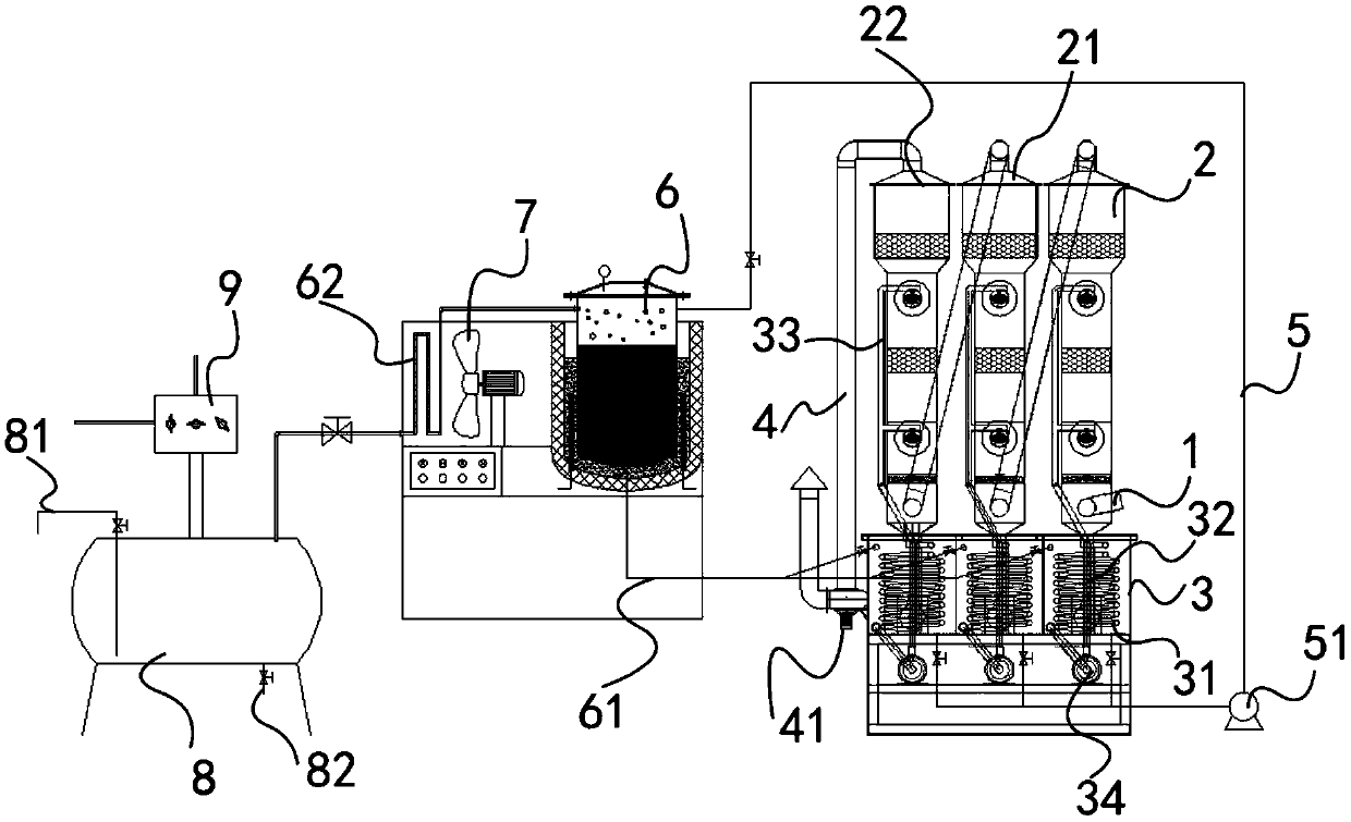
[0021] An embodiment of the organic waste gas treatment system of the present invention, such as figure 1 As shown, it comprises a spraying device and a vacuum distillation device, and the spraying device comprises the first spray tower 2, the second spray tower 21 and the third spray tower 22 connected in sequence, the inlet of the first spray tower 2 Air intake pipe 1 is installed on the gas end, exhaust pipe 4 is connected to the exhaust end of the third spray tower 22, exhaust fan 41 is installed on the exhaust pipe 4, the first spray tower 2, the second spray tower 21 and the liquid discharge end of the third spray tower 22 are all connected to the liquid storage tank 3, and the first spray tower 2, the second spray tower 21 and the third spray tower 22 all include the spray pipe 33 that the shower head is installed, and the spray The shower pipe 33 is sequentially connected with a liquid inlet pipe 32, a liquid inlet pump 34 is installed on the liquid pipe 32, a liquid s...


PUM


Abstract

The invention discloses an organic waste gas treatment system. The system comprises a spray device and a reduced pressure distillation device, the spray device comprises three spray towers which are connected in sequence, a gas inlet tube is mounted at the gas inlet end of the spray towers, the gas discharge end of the spray towers is connected with a gas discharge tube, the gas discharge tube isprovided with a gas discharge fan, the liquid discharge ends of the spray towers are connected with a liquid storage box, every spray tower includes a spray tube with a spray nozzle, the spray tubes are sequentially connected with the liquid inlet tubes, every liquid inlet tube is provided with a liquid feeding pump, the liquid discharge end of the liquid storage box is connected with a liquid suction tube, and the liquid suction tube is provided with a liquid suction pump; the reduced pressure distillation device includes a distillation kettle, the steam outlet of the distillation kettle is sequentially connected with a first condensing tube and a recovery tank, the recovery tank is connected with a vacuum generator, and a condensation fan is arranged at a corresponding position of the first condensing tube; and the liquid discharge end of the liquid suction tube is connected with the feeding end of the distillation kettle, and the material discharge end of the distillation kettle isconnected with the liquid inlet end of the liquid storage box through a material discharge tube. The organic waste gas treatment system of the invention can efficiently treat waste gas and recover volatile organic compounds.

Description

technical field [0001] The invention belongs to the technical field of waste gas treatment equipment, in particular to an organic waste gas treatment system. Background technique [0002] At present, the commonly used technologies for waste gas treatment include: UV photolysis and photocatalysis technology, activated carbon adsorption, RTO organic waste gas treatment and RCO organic waste gas treatment, etc. However, these technologies have some shortcomings: 1) UV photolysis and photocatalysis technology has low processing efficiency, and there are hidden dangers such as fire and explosion; 2) Activated carbon adsorption will cause secondary pollution and increase the cost of solid waste and hazardous waste treatment, and cause resource pollution. Waste; 3) The investment cost and operating cost of RTO and RCO organic waste gas treatment are high, and secondary pollution such as nitrogen oxides, carbon dioxide, and dioxins will also be generated. In short, the existing tec...

Claims


Application Information

Patent Timeline
IPC IPC(8): B01D53/18
CPCB01D53/1425B01D53/1487B01D53/18
Inventor 陈浩邹愚麦烱俊
Owner 佐敦(广东省)环境科技有限公司
Why Eureka
Try Eureka