Method and device for continuously feeding low-boiling point materials to high-pressure devices

A high-pressure device and low-boiling point technology, applied in the direction of using atmospheric pressure to chemically change substances, chemical instruments and methods, chemical/physical processes, etc., can solve the problem of easy generation of air bubbles at the feed pump, failure to feed normally, Easy to vaporize and other problems, to achieve the effect of reducing pump stop problems, ensuring continuity and ensuring stability

Active Publication Date: 2021-07-13
SHANDONG YUHUANG CHEM CO LTD
View PDF0 Cites 0 Cited by
  • Summary
  • Abstract
  • Description
  • Claims
  • Application Information

AI Technical Summary

Problems solved by technology

[0003] The invention provides a method for direct liquid feeding of low-boiling-point and easy-to-vaporize materials to the high-pressure system, which improves the problem of easy-to-vaporize low-boiling-point materials at room temperature, and the problem that air bubbles are easily generated at the feed pump and cannot be fed normally, and realizes Continuity, stability and uniformity of material transfer

Method used


Image

  • Method and device for continuously feeding low-boiling point materials to high-pressure devices

Examples


Embodiment 1

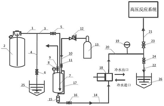
[0029] figure 1 The schematic diagram of the connection structure can be applied to the direct amination of isobutene to produce tert-butylamine synthesis reaction device (reaction system pressure is 5.0MPa) with low boiling point and easy vaporization material liquid ammonia (boiling point at normal pressure -33.5°C, saturated vapor pressure at normal temperature 0.922MPa (25 ℃)) feed.

[0030] The device includes the following components: low boiling point material storage tank (liquid ammonia storage tank) V-1, (liquid ammonia) pressure-resistant buffer tank V-2, protective gas (nitrogen) cylinder V-3, (liquid ammonia corrosion-resistant) inlet Material pump P-1, low-boiling point material (ammonia) absorption tank V-4, low-boiling point material (ammonia) absorption tank V-5, pressure-resistant (liquid ammonia corrosion-resistant) level gauge LA, corrosion-resistant ball valve HV1~ 7. Pressure reducing valve PCV-1, pressure gauge PI1~2;

[0031] The pipeline L1 is connec...

Embodiment 2

[0041] figure 1 The schematic diagram of the connection structure can be applied to the direct amination of isobutene to tert-butylamine synthesis reaction device (reaction system pressure is 5.0MPa) isobutene, a low-boiling and easy-to-vaporize material (boiling point at normal pressure -6.9°C, saturated vapor pressure at normal temperature 0.285MPa (25°C )) feed.

[0042] The device includes the following components: low boiling point material (isobutylene) storage tank V-1, (isobutylene) pressure buffer tank V-2, protective gas (nitrogen) cylinder V-3, (isobutylene corrosion resistant) feed pump P-1 , Low-boiling point material (isobutylene) absorption tank V-4, low-boiling point material (isobutylene) absorption tank V-5, pressure-resistant (isobutylene-resistant) liquid level gauge LA, corrosion-resistant ball valve HV1~7, pressure reducing valve PCV-1 , Pressure gauge PI1~2;

[0043] The pipeline L1 is connected to the bottom pipe of the isobutylene storage tank V-1, t...


PUM


Abstract

The invention belongs to the technical field of chemical reaction engineering, and relates to a method and a device for continuously feeding low-boiling point materials to high-pressure devices. The specific steps are: transport the low-boiling point material to the pressure-resistant buffer tank through the material storage tank; add a certain pressure of protective gas to the pressure-resistant buffer tank; the low-boiling point material enters the high-pressure reaction system from the pressure-resistant buffer tank through the metering pump ; When the material reserve in the pressure-resistant buffer tank decreases, repeat the steps to achieve continuous, stable and uniform feeding. The invention realizes the liquid feeding of low-boiling materials, and ensures the continuity, stability and uniformity of the feeding, effectively reduces the problem of stopping the pump caused by the bubbles caused by the vaporization of the materials, and ensures the stability of the reaction in the reactor .

Description

technical field [0001] The invention belongs to the technical field of chemical reaction engineering, and relates to a method and a device for continuously feeding low-boiling point materials to high-pressure devices. Background technique [0002] It is one of the difficulties for those skilled in the art to realize the continuous and stable feeding of low-boiling point and easy-to-vaporize materials (gas state at normal temperature and pressure, liquid state at low temperature or slightly high pressure) to the high-pressure reaction system. In this field, materials with low boiling point and easy vaporization are generally fed by gas, that is, the material is first vaporized into gas and then fed through a gas flow meter, but it is not suitable for materials that are in a liquid state under reaction pressure conditions. Condition. When the liquefied material is transported to the high-pressure reaction device through the high-pressure feed pump, the material is easy to vap...

Claims


Application Information

Patent Timeline
Patent Type & Authority Patents(China)
IPC IPC(8): B01J3/02B01J3/04
CPCB01J3/02B01J3/04
Inventor 谢忠蔡杰李林杰于丽萍杨德亮赵妍张晓龙贾鹏冲侯红霞王金书
Owner SHANDONG YUHUANG CHEM CO LTD
Why Eureka
Try Eureka