Fuel-free device for oil-sludge segmented drying, pyrolysis, incineration and secondary combustion of garbage sludge

A technology for segmented drying and sludge, applied in incinerators, combustion methods, combustion types, etc., can solve the problems of large floor space, high treatment costs, and difficulty in promotion, so as to reduce operating costs and increase the pyrolysis area. , the effect of self-combustion

Inactive Publication Date: 2019-04-02
李艺 +3
View PDF0 Cites 1 Cited by
  • Summary
  • Abstract
  • Description
  • Claims
  • Application Information

AI Technical Summary

Problems solved by technology

[0002] There are many kinds of equipment for waste treatment such as garbage sludge. In general, there are vertical pyrolysis furnaces, and the materials are baked in the lower part. This structure has poor ventilation and poor drying effect; The material is placed on the furnace grate to heat and dry, and the air permeability is improved, but the efficiency is low; there is also a horizontal rotary furnace for indirect heating and drying, although the entire layout is easy to operate, but it occupies a large area There are many supports for each equipment, and the investment is relatively large. Because the economic benefits of solid waste treatment are very low, the investment is large, and it is difficult to promote; the biggest problem wi

Method used


Image

  • Fuel-free device for oil-sludge segmented drying, pyrolysis, incineration and secondary combustion of garbage sludge
  • Fuel-free device for oil-sludge segmented drying, pyrolysis, incineration and secondary combustion of garbage sludge
  • Fuel-free device for oil-sludge segmented drying, pyrolysis, incineration and secondary combustion of garbage sludge

Examples


Embodiment Construction

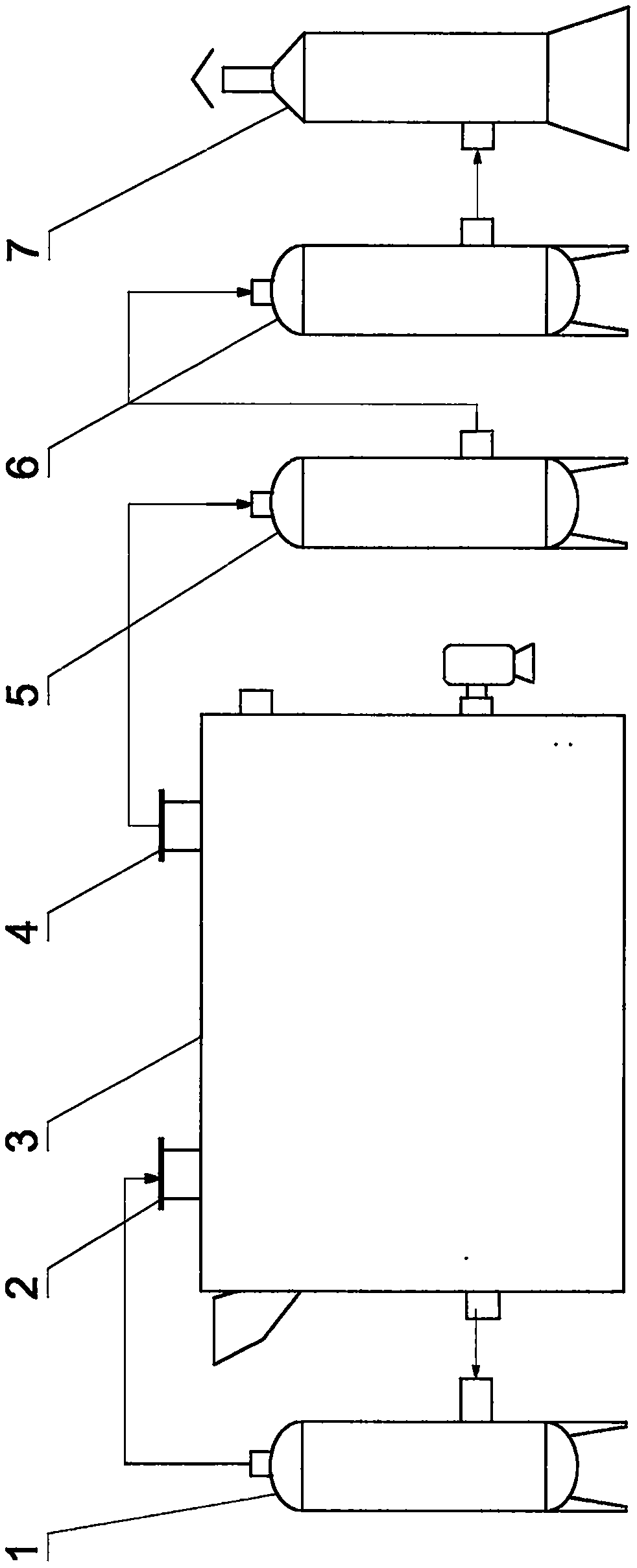
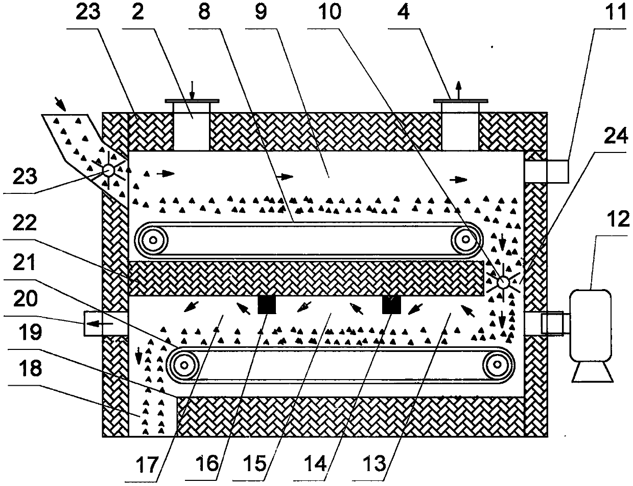
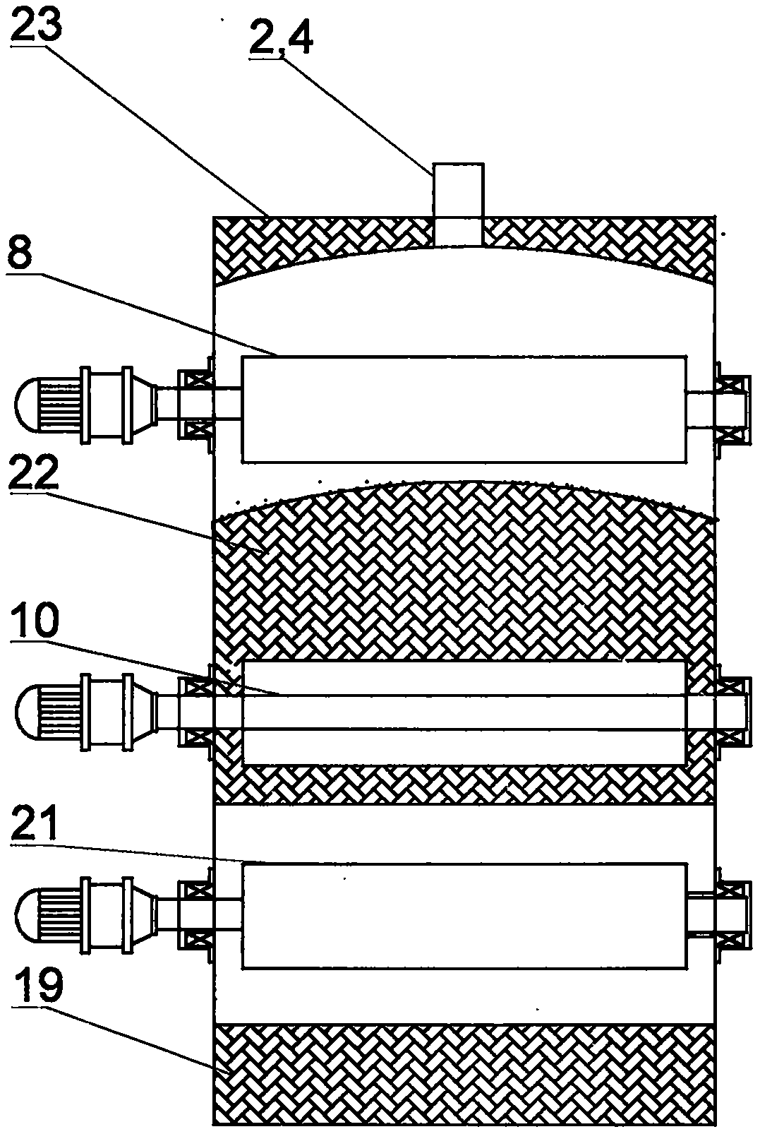
[0020] In the embodiment of the present invention, a garbage sludge sludge drying pyrolysis incineration and secondary combustion fuel-free device, the present invention consists of a quencher 1, a hot gas inlet 2, a multifunctional integrated furnace 3, an air outlet 4, and a denitrification device 5 , a desulfurizer 6, and an electrostatic precipitator 7, wherein the quench cooler 1 is connected and communicated with the hot gas inlet 2 through a connecting pipe; The other side of the upper part of the functional integrated furnace 3 is connected; the multifunctional integrated furnace 3 is connected and communicated with the denitrifier 5 through the connecting pipe, the denitrifier 5 is connected and communicated with the desulfurizer 6 through the connecting pipe, and the desulfurizer 6 is connected with the electrostatic precipitator through the connecting pipe The device 7 is connected and communicated, and the multifunctional integrated furnace 3 is connected and commun...


PUM


Abstract

A fuel-free device for oil-sludge segmented drying, pyrolysis, incineration and secondary combustion of garbage sludge is composed of a quench cooler, a hot gas inlet, a multifunctional integrated furnace, a gas outlet, a denitrator, a desulfurizer and an electrostatic dust collector. The quench cooler is connected with and communicates with the hot gas inlet through a connecting pipe. The hot gasinlet is arranged on one side of the upper portion of the multifunctional integrated furnace and communicates with the multifunctional integrated furnace. The gas outlet is arranged on one side of the upper portion of the multifunctional integrated furnace and communicates with the multifunctional integrated furnace. The multifunctional integrated furnace is connected with and communicates with the denitrator through a connecting pipe. The denitrator is connected with and communicates with the desulfurizer through a connecting pipe. The desulfurizer is connected with and communicates with theelectrostatic dust collector through a connecting pipe. The multifunctional integrated furnace is connected with and communicates with the quench cooler through a connecting pipe. Multiple function areas are arranged in the multifunctional integrated furnace, drying, pyrolysis, incineration and secondary combustion are integrated, and environment protection treatment of garbage and the like is perfectly achieved by cooperating with the tail gas purification function.

Description

technical field [0001] The invention relates to the field of environmental protection and chemical industry, in particular to a device for drying, pyrolysis and incineration of garbage sludge and oil sludge in stages, and a fuel-free device for secondary combustion. Background technique [0002] There are many kinds of equipment for waste treatment such as garbage sludge. In general, there are vertical pyrolysis furnaces, and the materials are baked in the lower part. This structure has poor ventilation and poor drying effect; The material is placed on the furnace grate to heat and dry, and the air permeability is improved, but the efficiency is low; there is also a horizontal rotary furnace for indirect heating and drying, although the entire layout is easy to operate, but it occupies a large area There are many supports for each equipment, and the investment is relatively large. Because the economic benefits of solid waste treatment are very low, the investment is large, a...

Claims


Application Information

Patent Timeline
IPC IPC(8): F23G5/04F23G5/027F23G5/16F23G5/44F23G7/00F23J15/02
CPCF23G5/04F23G5/027F23G5/165F23G5/44F23G5/444F23G7/001F23G2201/10F23G2201/302F23G2201/303F23G2202/103F23G2205/124F23G2209/12F23J15/02F23J15/025F23J2215/10F23J2215/20F23J2217/102
Inventor 李艺肖国华欧阳李黎江钰
Owner 李艺
Why Eureka
Try Eureka